Apparatus for auto-regulating input power source of driver
a technology of input power source and driver, which is applied in the direction of electric variable regulation, process and machine control, instruments, etc., can solve the problems of wasteful 12v supply of driver, unflexible conventional way of providing power by constant voltage source, and unnecessary driving loss
- Summary
- Abstract
- Description
- Claims
- Application Information
AI Technical Summary
Benefits of technology
Problems solved by technology
Method used
Image

Examples
first embodiment
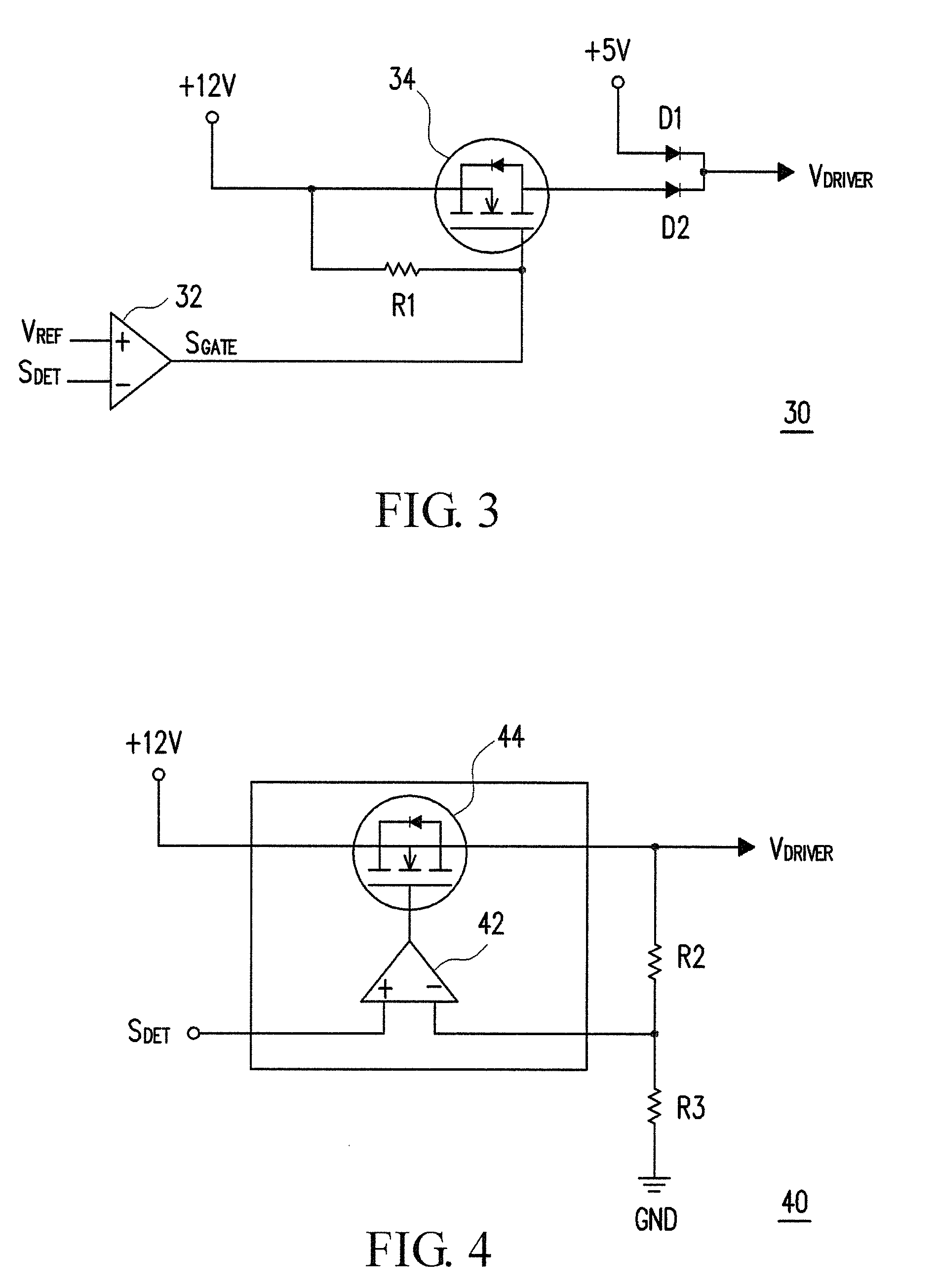
[0020]FIG. 3 is a circuit diagram of a controller according to the invention. As shown in FIG. 3, the aforesaid criterion for determining whether the load is heavy or light may further be implemented via a reference signal VREF. The reference signal VREF may be a voltage value of a resistance divider (not shown). The controller 30 may compare the detection signal SDET and the reference signal VREF by a comparator 32. The first input end of the comparator 32 receives the reference signal VREF, and the second input end of the comparator 32 receives the detection signal SDET. Afterward, the power source is switched to provide the operation voltage VDRIVER to the driver (not shown) according to a comparative result SGATE of the comparator 32. For example, the system is in the light load state and the output of the comparator 32 is a logic high level when the detection signal SDET is not higher than the reference signal VREF, and the first voltage (+5V) may be provided to the driver to w...
second embodiment
[0022]FIG. 4 is a circuit diagram of a controller according to the invention. As shown in FIG. 4, the controller 40 is a low dropout regulator (LDO). The controller 40 includes a resistor R2, a resistor R3, a semiconductor switch 44, and an operational amplifier 42. The semiconductor switch 44 may be an N-TYPE semiconductor switch. The first source / drain electrode of the semiconductor switch 44 is coupled to the second voltage (+12V). The second source / drain electrode of the semiconductor switch 44 is coupled to the first end of the resistor R2, and the operation voltage VDRIVER is provided from the second source / drain electrode of the semiconductor switch 44. The first end of the resistor R3 is coupled to the second end of the resistor R2. The second end of the resistor R3 is coupled to a ground voltage GND. The “+” input end of the operational amplifier 42 is coupled to the detection signal SDET. The “−” input end of the operational amplifier 42 is coupled to the first end of the ...
third embodiment
[0023]FIG. 5 is a circuit diagram of a controller according to the invention. As shown in FIG. 5, the controller 50 is a linear voltage regulator. The controller 50 includes resistors R4 and R5, capacitors C1 and C2, a semiconductor switch 54, and an operational amplifier 52. The semiconductor switch 54 may be an N-TYPE semiconductor switch. The second source / drain electrode of the semiconductor switch 54 is coupled to the second voltage (+12V). The first source / drain electrode of the semiconductor switch 54 is coupled to the first end of the capacitor C1 and the first end of the resistor R5, and the operation voltage VDRIVER is provided by the first source / drain electrode of the semiconductor switch 54. The “+” input end of the operational amplifier 52 is coupled to the detection signal SDET, and the “−” input end of the operational amplifier 52 is coupled to the second end of the resistor R5. In addition, the output end of the operational amplifier 52 is coupled to the gate electr...
PUM
 Abstract
Description
Claims
Application Information
 - R&D
- Intellectual Property
- Life Sciences
- Materials
- Tech Scout
- Unparalleled Data Quality
- Higher Quality Content
- 60% Fewer Hallucinations
Browse by: Latest US Patents, China's latest patents, Technical Efficacy Thesaurus, Application Domain, Technology Topic, Popular Technical Reports.
© 2025 PatSnap. All rights reserved.Legal|Privacy policy|Modern Slavery Act Transparency Statement|Sitemap|About US| Contact US: help@patsnap.com