
Gate Drive Circuit, Display Device Having the Same and Method of Manufacturing the Gate Drive Circuit

a gate drive circuit and display device technology, applied in semiconductor devices, digital storage, instruments, etc., can solve the problems of unstable gate terminal signal of pull-up element, difficult pull-up function of pull-up element at gate during interval period, etc., and achieve the effect of enhancing the driving reliability of the gate drive circui

Active Publication Date: 2010-07-01
SAMSUNG DISPLAY CO LTD
View PDF4 Cites 45 Cited by
  • Summary
  • Abstract
  • Description
  • Claims
  • Application Information

AI Technical Summary

Benefits of technology

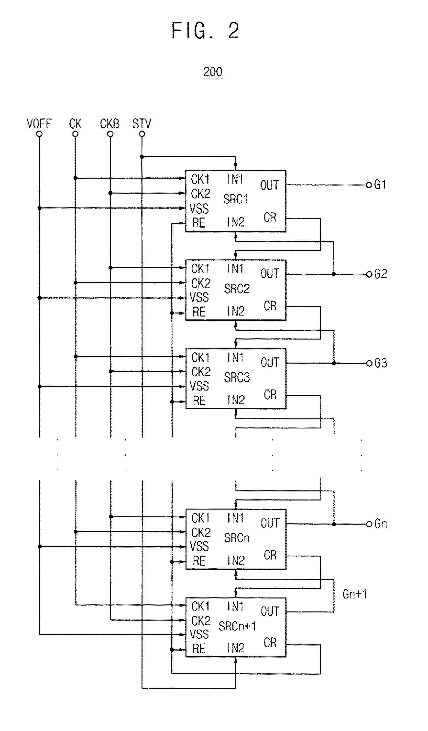
The present invention provides a gate drive circuit that includes a shift register with multiple stages connected to each other. Each stage includes a first transistor with a first channel length that outputs a clock signal as a gate signal in response to an external device. The circuit also includes a second transistor with a second channel length that is longer than the first channel length. The second transistor has a floating electrode and a drain electrode with a plurality of drain electrode bars. The circuit also includes a buffering part, a carry part, a third holding part, and a switching part. The circuit allows for the efficient and reliable control of the gate signal in a display device.

Problems solved by technology

A signal of a gate terminal of the pull-up element may be made unstable due to the ripple.
When a channel width W of a transistor for stabilizing a gate terminal of the pull-up element is increased to prevent the ripple from generating, a pull-up function of the pull-up element at a gate may be difficult during an interval period.

Method used


Image

  • Gate Drive Circuit, Display Device Having the Same and Method of Manufacturing the Gate Drive Circuit
  • Gate Drive Circuit, Display Device Having the Same and Method of Manufacturing the Gate Drive Circuit
  • Gate Drive Circuit, Display Device Having the Same and Method of Manufacturing the Gate Drive Circuit

Examples


Embodiment Construction

[0039]The present invention is described more fully hereinafter with reference to the accompanying drawings, in which exemplary embodiments of the present invention are shown. The present invention may, however, be embodied in many different forms and should not be construed as limited to exemplary embodiments set forth herein. Rather, exemplary embodiments are provided so that this disclosure will be thorough and complete, and will fully convey the scope of the present invention to those skilled in the art. In the drawings, the sizes and relative sizes of layers and regions may be exaggerated for clarity.

[0040]The terminology used herein is for the purpose of describing particular exemplary embodiments only and is not intended to be limiting of the present invention.

[0041]Hereinafter, the present invention will be explained in detail with reference to the accompanying drawings.

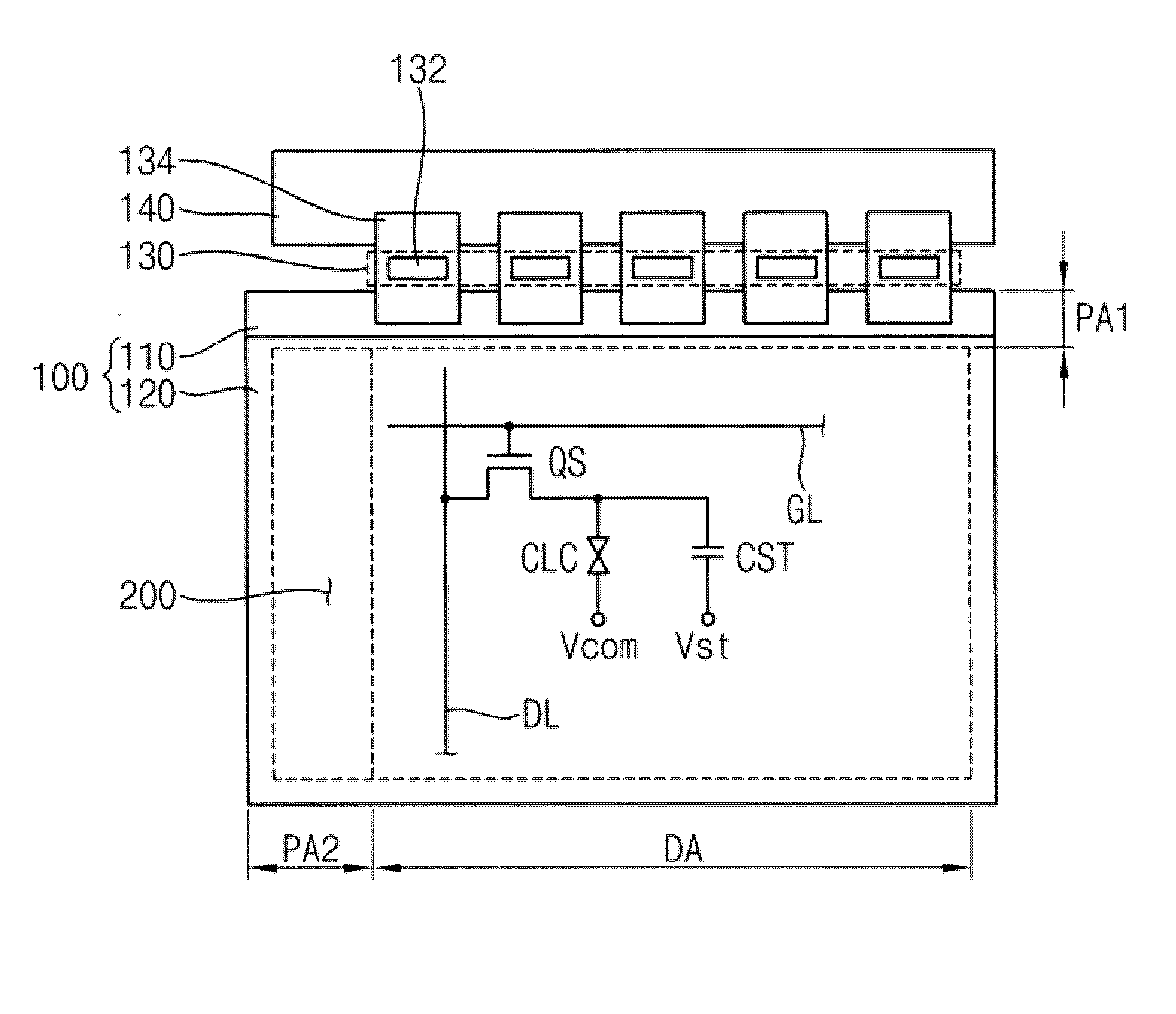
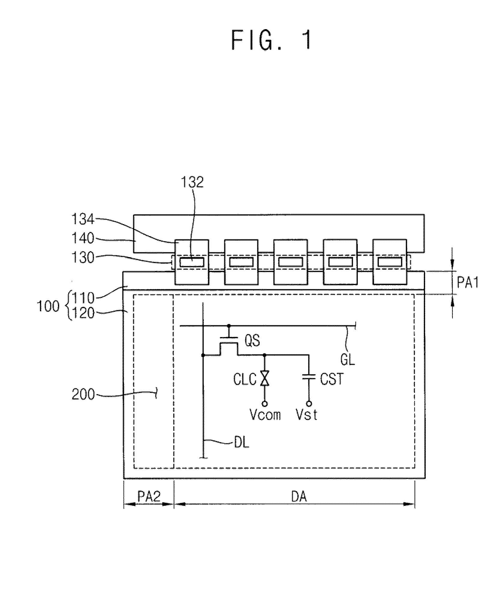
[0042]FIG. 1 is a plan view schematically illustrating a display device according to an exemplary embodime...


PUM


Abstract

A gate drive circuit includes a shift register having stages connected to each other in series. An (m)-th stage (‘m’ is a natural number) includes an output part, a discharging part, a first holding part and a second holding part. The output part outputs the first clock signal as a gate signal in response to a first clock signal provided from an external device and discharges the gate signal in response to a second input signal. The output part includes a first transistor having a first channel length. The discharging part discharges a signal of the first node to the second voltage level. The first holding part maintains a signal of the first node at a level of the gate signal, and is discharged to the second voltage level. The first holding part includes a second transistor having a second channel length that is longer than the first channel length. The second holding part maintains a signal of the first node at a level of the second voltage level.

Description

CROSS-REFERENCE TO RELATED APPLICATION[0001]This application claims priority under 35 U.S.C. §119 to Korean Patent Application No. 2008-134276, filed on Dec. 26, 2008 in the Korean Intellectual Property Office (KIPO), the contents of which are herein incorporated by reference in their entirety.BACKGROUND OF THE INVENTION[0002]1. Field of the Invention[0003]Exemplary embodiments of the present invention relate to a gate drive circuit, a display device having the gate drive circuit and a method of manufacturing the gate drive circuit. More particularly, exemplary embodiments of the present invention relate to a gate drive circuit for enhancing reliability thereof, a display device having the gate drive circuit and a method of manufacturing the gate drive circuit.[0004]2. Description of Related Art[0005]Generally, a liquid crystal display (LCD) device includes an array substrate, an opposing substrate and a liquid crystal layer interposed between the array substrate and the opposing su...

Claims


Application Information

Patent Timeline
Patent Type & Authority Applications(United States)
IPC IPC(8): G09G3/36G11C19/00H01L21/82
CPCG09G3/3677G11C19/184H01L27/1288G02F1/133G09G3/20G09G3/36
Inventor KIM, KYUNG-WOOKKIM, JONG-HOON
Owner SAMSUNG DISPLAY CO LTD
Learn More