Backlight brightness control for panel display device

a display device and backlight brightness technology, applied in the direction of electric variable regulation, process and machine control, instruments, etc., can solve the problems of limitation of the number of adjustment steps of backlight brightness, and increasing power consumption of liquid crystal displays. achieve the effect of increasing the number of effective adjustment steps and reducing circuit siz

Active Publication Date: 2010-07-01
SYNAPTICS JAPAN GK
View PDF7 Cites 96 Cited by
  • Summary
  • Abstract
  • Description
  • Claims
  • Application Information

AI Technical Summary

Benefits of technology

[0016]When the backlight brightness is changed in the middle of each frame period, the backlight brightness actually perceived by the human eyes is the average of the backlight brightness in each frame period. Therefore, intermediate levels of the backlight brightness are virtually achieved by controlling backlight brightness in the middle of each frame period. This approach allows increasing the number of the effective adjustment steps of the backlight brightness with reduced circuit size.

Problems solved by technology

One problem in recent LCD (liquid crystal display) devices, specifically LCD devices mounted on portable terminals, is increased power consumption.
As the LCD panel is grown in size with an improved resolution, the power consumption of the liquid crystal display increases year by year.
One issue in optimization of the brightness control of the backlight is limitation of the number of adjustment steps of the backlight brightness.
However, the adjustment in 256 steps may be insufficient for a specific control algorithm of the backlight brightness.
This undesirably leads to reduction in the number of adjustment steps of the backlight brightness for the dark use environment.
When the number of adjustment steps of the backlight brightness, which depends on the environment light intensity, is reduced below the number of steps necessary for providing desired picture contrast, the backlight brightness is not suitably controlled on the picture level.
However, when the number of adjustment steps of the backlight brightness, which depends on the environment light intensity, becomes smaller than 64, the backlight brightness may be improperly controlled based on the picture level.
However, such approach undesirably increases the circuit size.
This increases the circuit size of the brightness control circuit.
In addition, the circuit size of the backlight drive circuit is undesirably increased when the backlight drive circuit is configured so as to process the PWM signal that is variable in multiple steps.

Method used


Image

  • Backlight brightness control for panel display device
  • Backlight brightness control for panel display device
  • Backlight brightness control for panel display device

Examples


Embodiment Construction

[0026]The invention will be now described herein with reference to illustrative embodiments. Those skilled in the art will recognize that many alternative embodiments can be accomplished using the teachings of the present invention and that the invention is not limited to the embodiments illustrated for explanatory purposes.

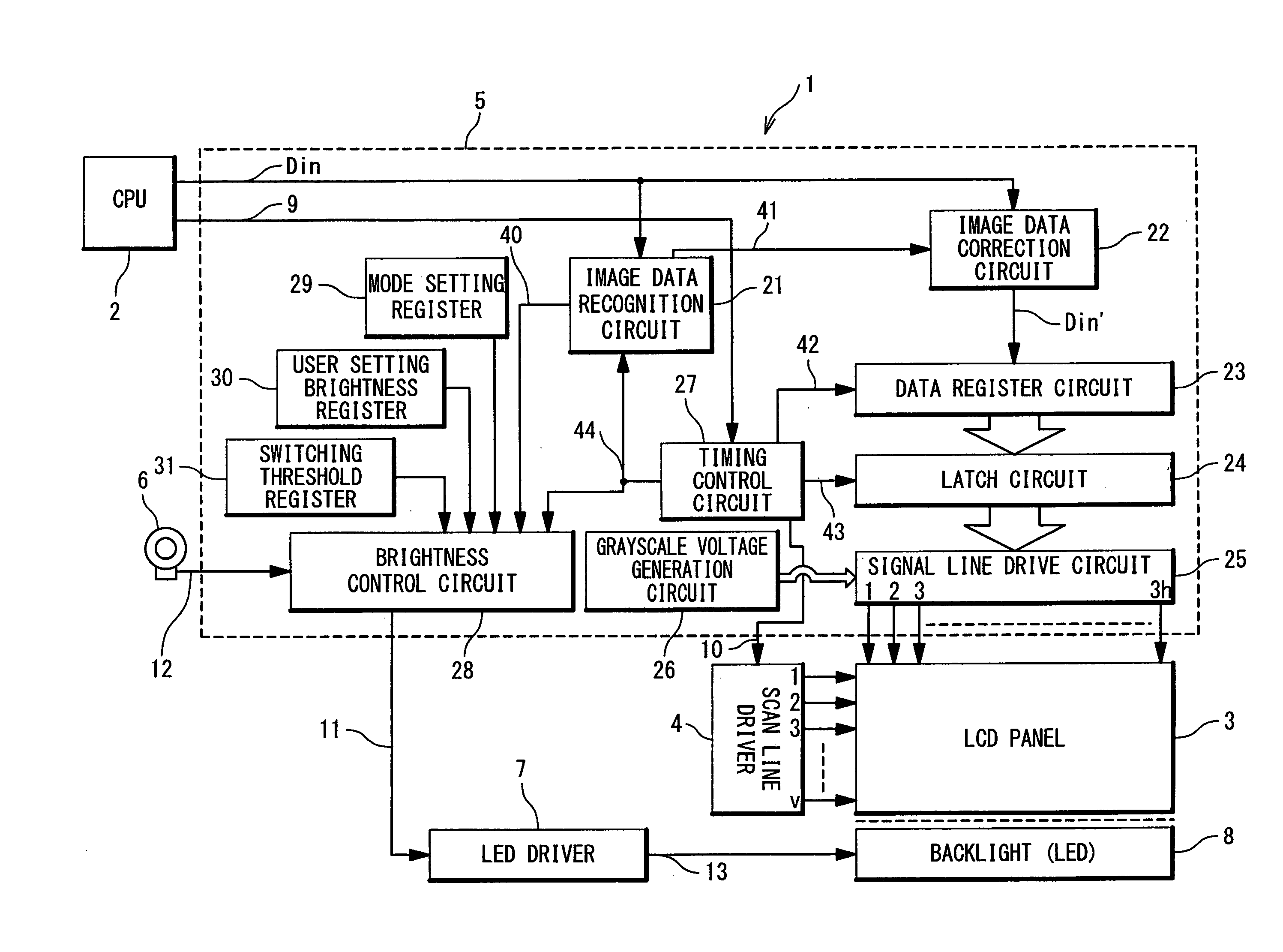
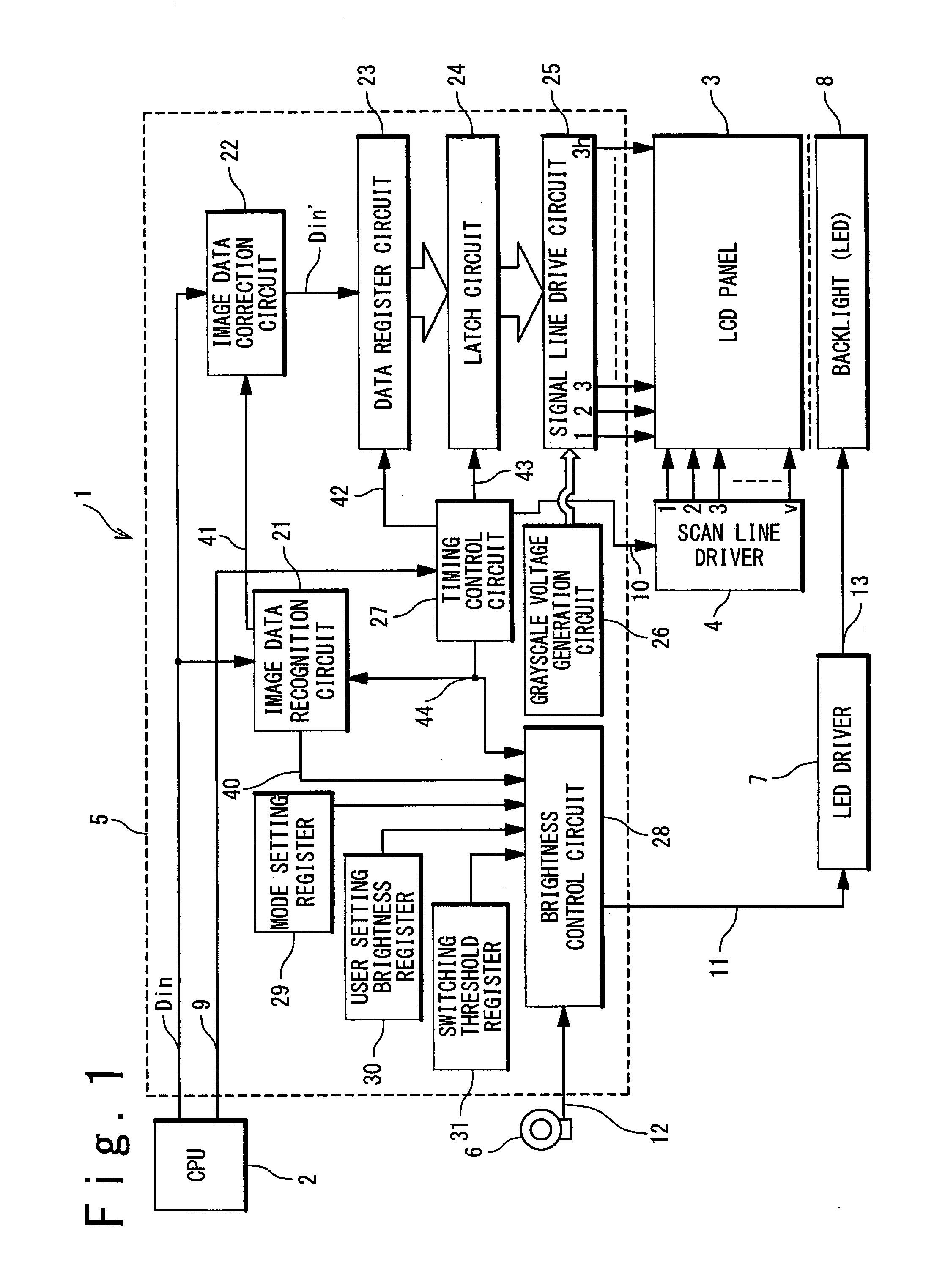
[0027]FIG. 1 is a block diagram showing an exemplary configuration of a liquid crystal display device 1 in one embodiment of the present invention. The liquid crystal display device 1 is configured to display an image in accordance with image data Din supplied from a CPU (Central Processing Unit) 2, and includes an LCD (Liquid Crystal Display) panel 3, a scan line driver 4, an LCD driver 5, an environment light sensor 6, an LED (Light Emitting Diode) driver 7, and a backlight 8. In this embodiment, the backlight 8 includes an LED and a light guide, and illuminates the LCD panel 3.

[0028]The LCD panel 3 includes signal lines (or data lines), scan lines (or gate lin...


PUM


Abstract

A display device is provided with a display panel; a backlight which illuminates the display panel; and a backlight brightness controller controlling a brightness of the backlight so that the brightness of the brightness is variable in the middle of each frame period.

Description

INCORPORATION BY REFERENCE[0001]This application claims the benefit of priority based on Japanese Patent Application No. 2008-319692, filed on Dec. 16, 2008, the disclosure of which is incorporated herein by reference.BACKGROUND OF THE INVENTION[0002]1. Field of the Invention[0003]The present invention relates to a display device, a display panel driver, and a backlight drive method, and especially relates to a brightness control of backlight of the display device.[0004]2. Description of the Related Art[0005]One problem in recent LCD (liquid crystal display) devices, specifically LCD devices mounted on portable terminals, is increased power consumption. As the LCD panel is grown in size with an improved resolution, the power consumption of the liquid crystal display increases year by year. The backlight is large is power consumption, and accordingly reduction of the power consumption of the backlight is effective means for reduction of the total power consumption of the liquid cryst...

Claims


Application Information

Patent Timeline
Patent Type & Authority Applications(United States)
IPC IPC(8): G09G5/10H05B37/02G06F3/038
CPCG09G3/3406G09G2320/064G09G2320/0646G09G2330/021G09G2360/144G09G2360/16H05B33/0854H05B45/325H05B45/10H05B45/12
Inventor NOSE, TAKASHIFURIHATA, HIROBUMI
Owner SYNAPTICS JAPAN GK
Why Eureka
Try Eureka