

Laser image display, and optical integrator and laser light source package used in such laser image display
- Summary
- Abstract
- Description
- Claims
- Application Information
AI Technical Summary
Benefits of technology
Problems solved by technology
Method used
Image

Examples
first embodiment
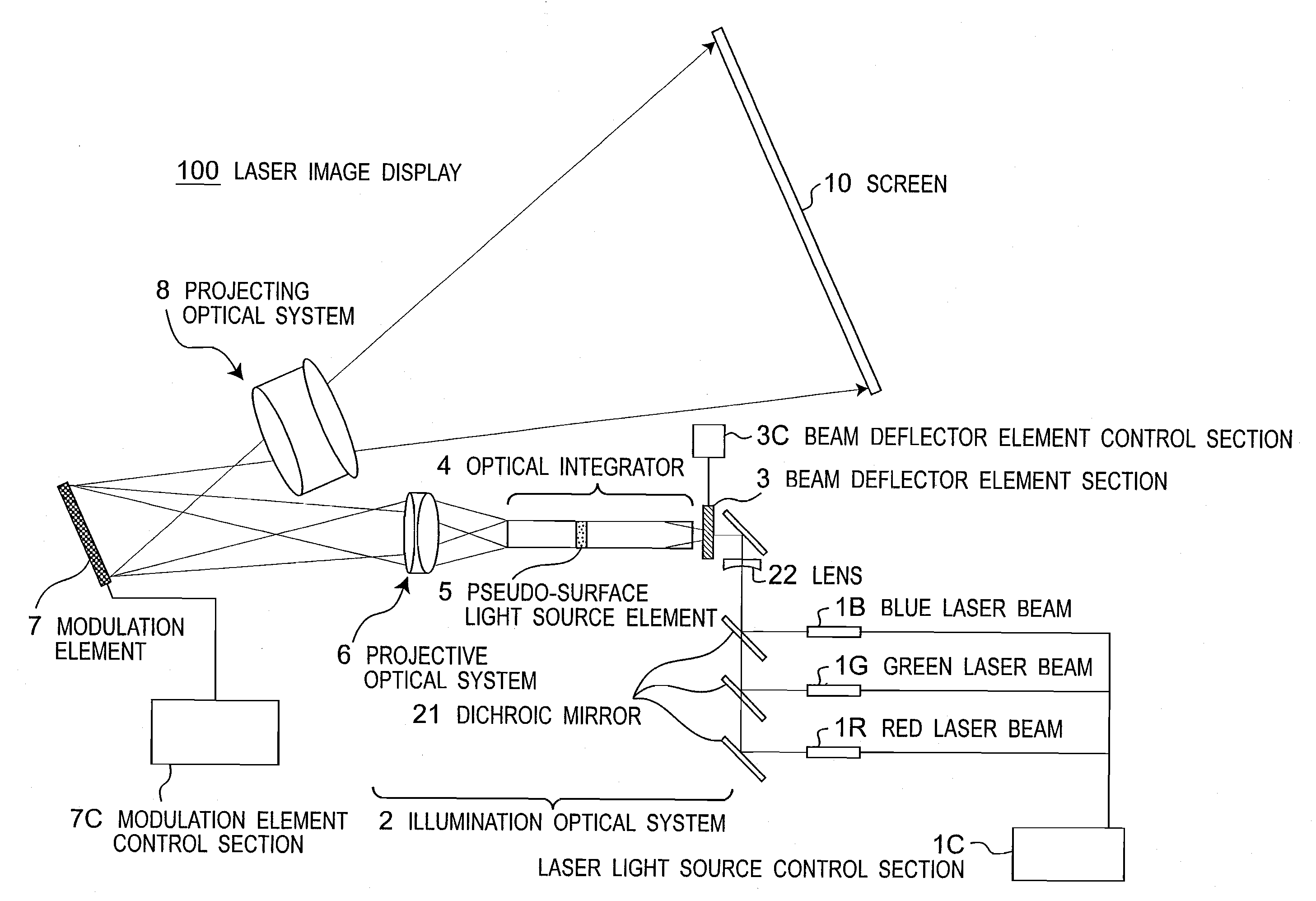
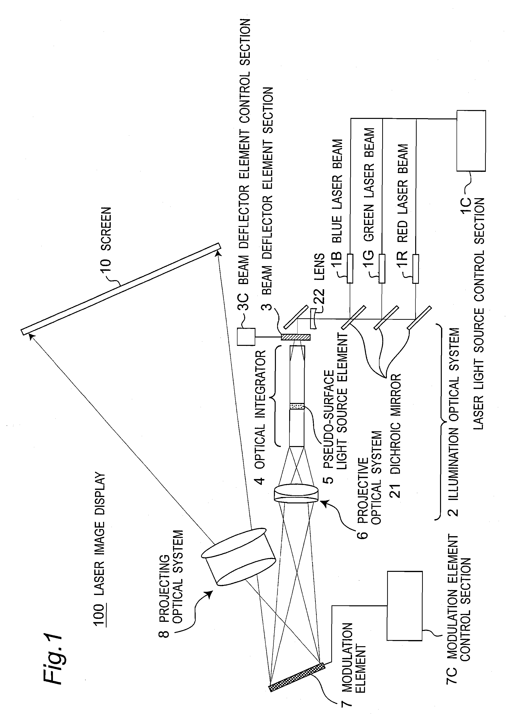
[0125]The first embodiment of the present invention is a laser image display. The laser image display is a projection display (laser display). FIG. 1 is a schematic configuration diagram of the laser image display 100 according to the first embodiment.
[0126]The laser image display 100 includes laser light sources of three colors of red (R) laser light source 1R, green (G) laser light source 1G, and blue (B) laser light source 1B; a laser light source control section 1C which performs drive control of the laser light sources 1R, 1G, and 1B; a dichroic mirror 21 which reflects or transmits the laser light; a lens 22 (e.g., diverging lens); a beam deflector element section 3 which deflects the advancing direction of the laser light; a beam deflector element control section 3C which drives and controls the beam deflector element section 3; an optical integrator 4 which guides the laser light; a pseudo-surface light source element 5 which is preferably configured inside the optical integ...
second embodiment
[0232]FIG. 14 is a schematic diagram showing another example of an illumination optical system in the laser image display according to the present invention. In the present example, the laser light emitted from the laser light source is passed through the lens 22 and the vibration mirror 3M capable of vibrating in an oscillating manner, and enters a multi-rod integrator 1401 having a rectangular exit end face. The multi-rod integrator 1401 has a configuration of sandwiching a birefringence pseudo-surface light source element 1403, and has a lens array 1405 at the incident end face.
[0233]The illumination optical system of the second embodiment performs beam deflection angle control of the incident laser light of the multi-rod integrator 1401 (optical integrator) so that the light source image of the laser light temporally changes by cooperative operation of the vibration mirror 3M and the lens array 1405 formed on the multi-rod integrator 1401. In the present illumination optical sys...
third embodiment
[0239]FIG. 15 is a schematic diagram of a laser image display 100 according to a third embodiment of the present invention. In FIG. 15, same reference numerals are used for components same as in FIG. 1.
[0240]The laser lights emitted from the laser light sources 1R, 1G, and 1B of RGB three colors are respectively guided to an illumination optical system 202 which is an optical system for emitting the laser light for illuminating a two-dimensional modulation element 271 with micro-lens array. The illumination optical system 202 includes rotatable lenticular lens arrays 3a, 3b configuring the beam deflector element section, the optical integrator 4, the pseudo-surface light source element 5, and a projective optical system 206, where the laser light having a substantially rectangular and uniform intensity distribution is illuminated on the modulation element 271. The projective optical system 206 includes a mirror 261 and a field lens 262. Each color laser light is subjected to modulat...
PUM
 Abstract
Description
Claims
Application Information