Tissue sealing system and apparatus

a tissue sealing and tissue technology, applied in the field of tissue sealing systems and apparatuses, can solve the problems of increasing the procedure time, limiting the ability of the surgeon to direct the spray, and the need for the surgeon or other medical professionals to carefully monitor, so as to achieve the effect of convenient repositioning

Active Publication Date: 2010-07-01
BAXTER INT INC +1
View PDF12 Cites 20 Cited by
  • Summary
  • Abstract
  • Description
  • Claims
  • Application Information

AI Technical Summary

Benefits of technology

[0013]The inner diameter of the ring member, the teeth, and an outer wall of the sealant component passageways define a plurality of apertures at the distal end of the elongate delivery tube for gas in the passageway to first be exposed to the two components as the components are simultaneously ejected from the elongate delivery tube, thereby spraying the tissue sealant onto a target tissue site. The rounded or angled distal end may be easily repositioned by simply rotating the elongate delivery tube to direct a conical spray of tissue sealant to a different portion of a target tissue site.

Problems solved by technology

While such tissue sealing systems have been described and used, these systems limit the ability of the surgeon to direct the spray.
This interrupted application of tissue sealant undesirably increases procedure time.
Another disadvantage of existing gas driven tissue delivery systems is the need for the surgeon or other medical professionals to carefully monitor the gas pressure introduced via the trocar to a bodily cavity.
With such gas driven tissue delivery systems, an unacceptable increase of intracavity pressure may be realized if no venting is performed.
However, these solutions require nearly-constant monitoring of intracavity pressure and pressure of gas, such as CO2 or helium, used in the spray device or otherwise introduced into the bodily cavity.

Method used


Image

  • Tissue sealing system and apparatus
  • Tissue sealing system and apparatus
  • Tissue sealing system and apparatus

Examples


Embodiment Construction

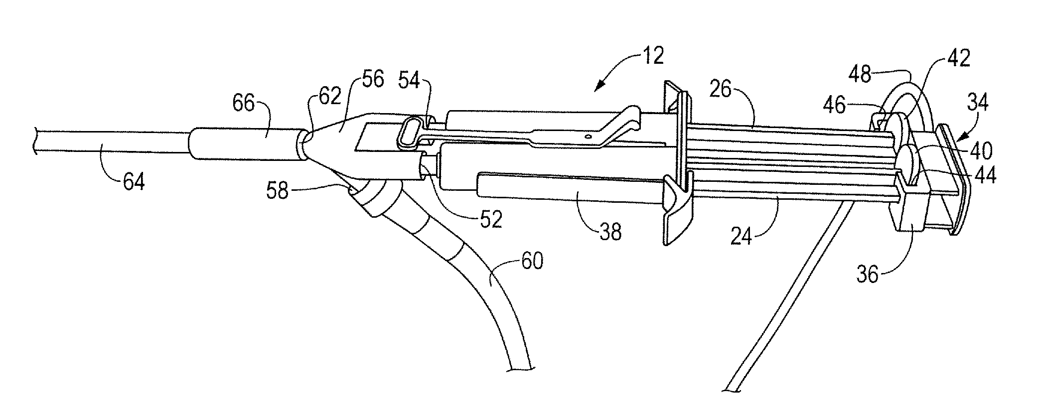
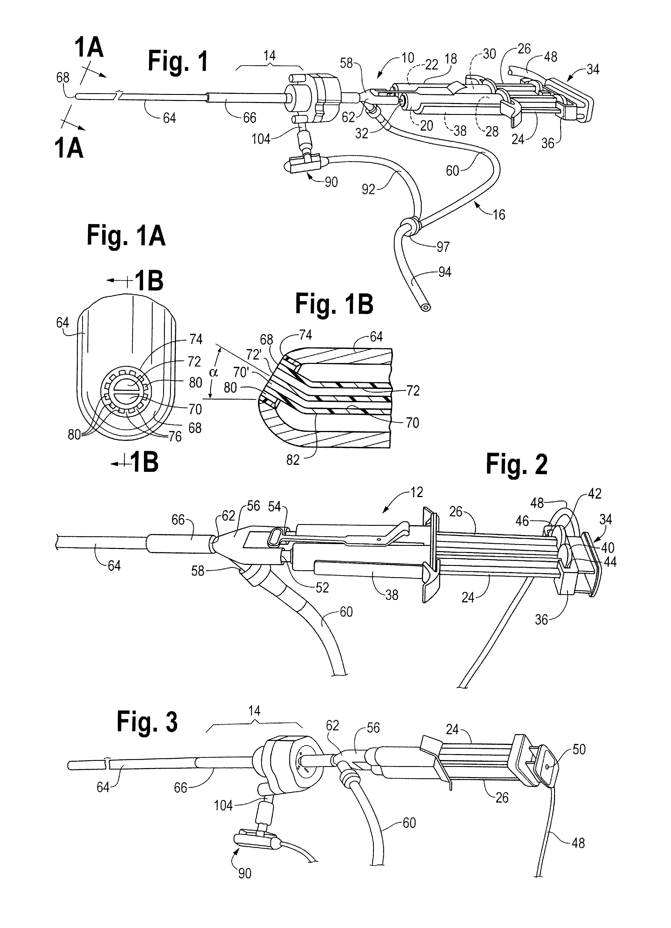
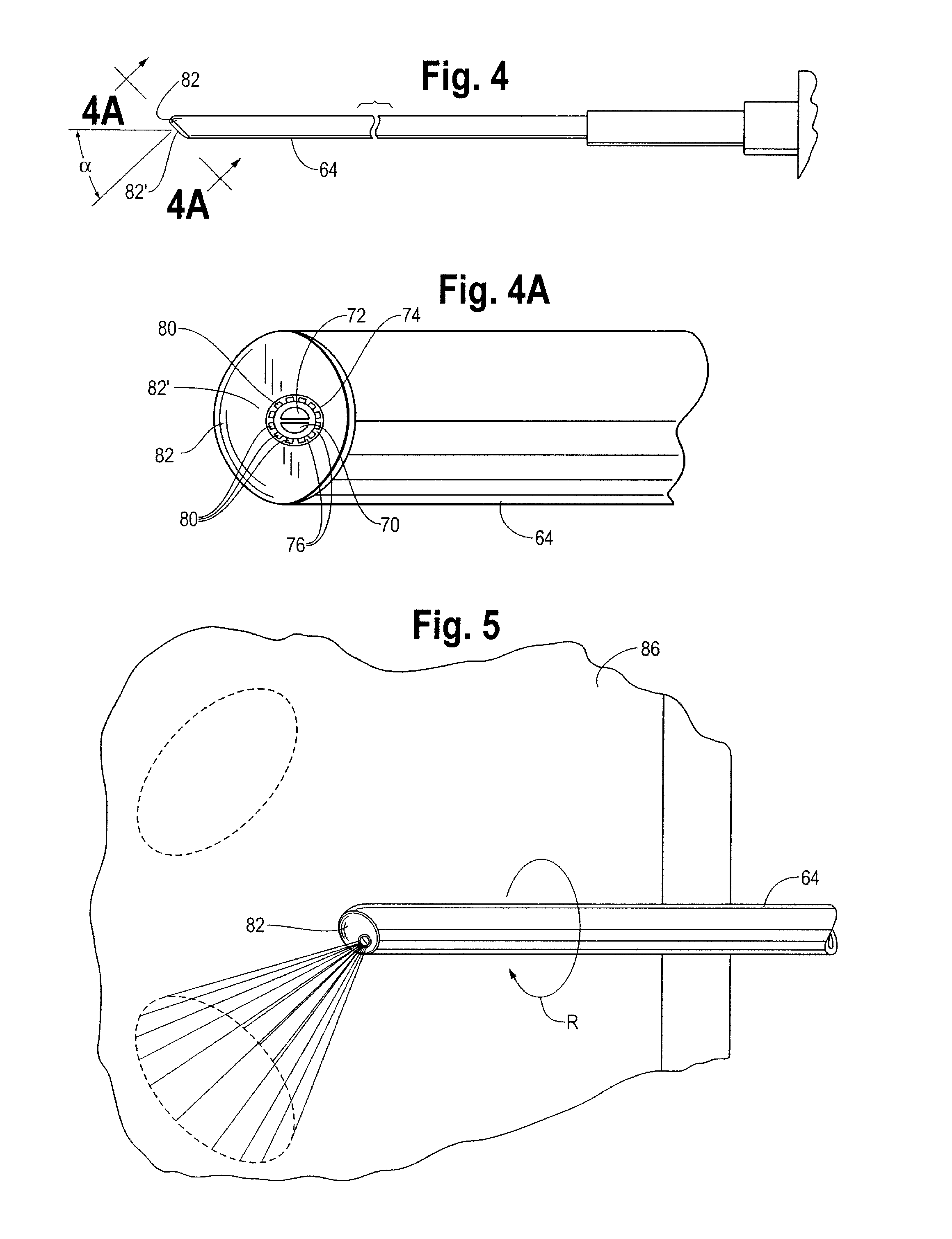
[0026]The laparoscopic tissue sealant spray apparatus and system 10 of the present disclosure includes a tissue sealant spray assembly 12, a trocar assembly 14, and a network of gas supply tubing 16. The tissue sealant spray assembly 12 has a barrel assembly 18 defining a compartment for a tissue sealant. The fluid to be delivered is preferably a tissue sealant, and is most preferably a multi-component tissue sealant, such as a two-component sealant including thrombin and fibrinogen. Much of the tissue sealant spray apparatus and system, up to and including a generally Y-shaped spray adapter member, may be as described in U.S. Pat. No. 7,537,174, wherein the components of the apparatus and system are described in greater detail than is provided here.

[0027]In the case of a two-component sealant where the components must be isolated from one another until their application to a target site, the barrel assembly 18 includes two interior bores 20, 22, with each component stored in one of...


PUM


Abstract

A laparoscopic tissue sealant spray apparatus and system having a laparoscopic tissue sealant spray assembly combined with a trocar assembly, the tissue sealant spray assembly having an elongate delivery tube. A spray outlet at a distal end of the elongate delivery tube may be rounded or angled. A ring member provided at the distal end of the elongate delivery tube directs a spray cone toward a portion of a target tissue site, and the spray cone may be repositioned to a different portion of the target tissue site by rotation of the elongate delivery tube. The trocar assembly includes a vent opening that connects to a venting valve member that provides a vent path which passively opens upon operation of the tissue sealant spray assembly, avoiding excessive pressure build-up within a body cavity.

Description

REFERENCE TO RELATED APPLICATIONS[0001]This application claims the benefit of the filing date of U.S. Provisional Application No. 61 / 141,437, filed Dec. 31, 2008, the disclosure of which is incorporated herein by reference.BACKGROUND[0002]1. Filed of the Disclosure[0003]This disclosure is generally directed to systems for applying a sealant to a work surface and, more particularly, to an apparatus and system for applying tissue sealant to biological tissue employing structure that facilitates controlled spray application of tissue sealant and passive control of gas pressure.[0004]2. Description of the Related Art[0005]Various apparatus and systems have been disclosed for application of tissue sealants. One such disclosure is U.S. Pat. No. 7,537,174, entitled “Hand Triggered Tissue Sealant Spray Apparatus and System,” the entirety of which is incorporated herein by reference. An effective tissue sealant is a two-component tissue sealant made up of fibrinogen and thrombin. Because the...

Claims


Application Information

Patent Timeline
Patent Type & Authority Applications(United States)
IPC IPC(8): A61B17/03A61B17/34
CPCA61B17/00491A61B17/3474A61B2017/00495A61B2017/00522
Inventor REDL, HEINZKHAKPOUR, ZAFARFORTELNY, RENE
Owner BAXTER INT INC
Why Eureka
Try Eureka