[0009]It is an object of the present invention to provide a cast-in channel which will overcome the aforementioned disadvantages and which will have adequate
corrosion protection, although connectors are provided to fixedly attach the anchoring members to the channel body. Another object of the present invention is to provide a connector for such a cast-in channel.
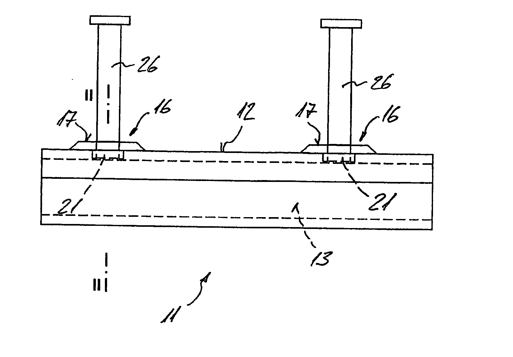
[0012]The anchoring members can be attached externally to the body of the channel with respect to the receiving space. This allows the channel body to be provided with an
infill, while the anchoring member can still be attached to the channel body. In addition, different types of anchoring members can be attached to the same channel body, which also allows the cast-in channel to be adapted to different load requirements at the construction site, if necessary. Even a previously assembled cast-in channel can be easily adapted to a different type of load, also directly at the construction site, for example. Yet, until the anchoring members are attached to the channel body, the cast-in channel occupies a minimum volume during shipping.
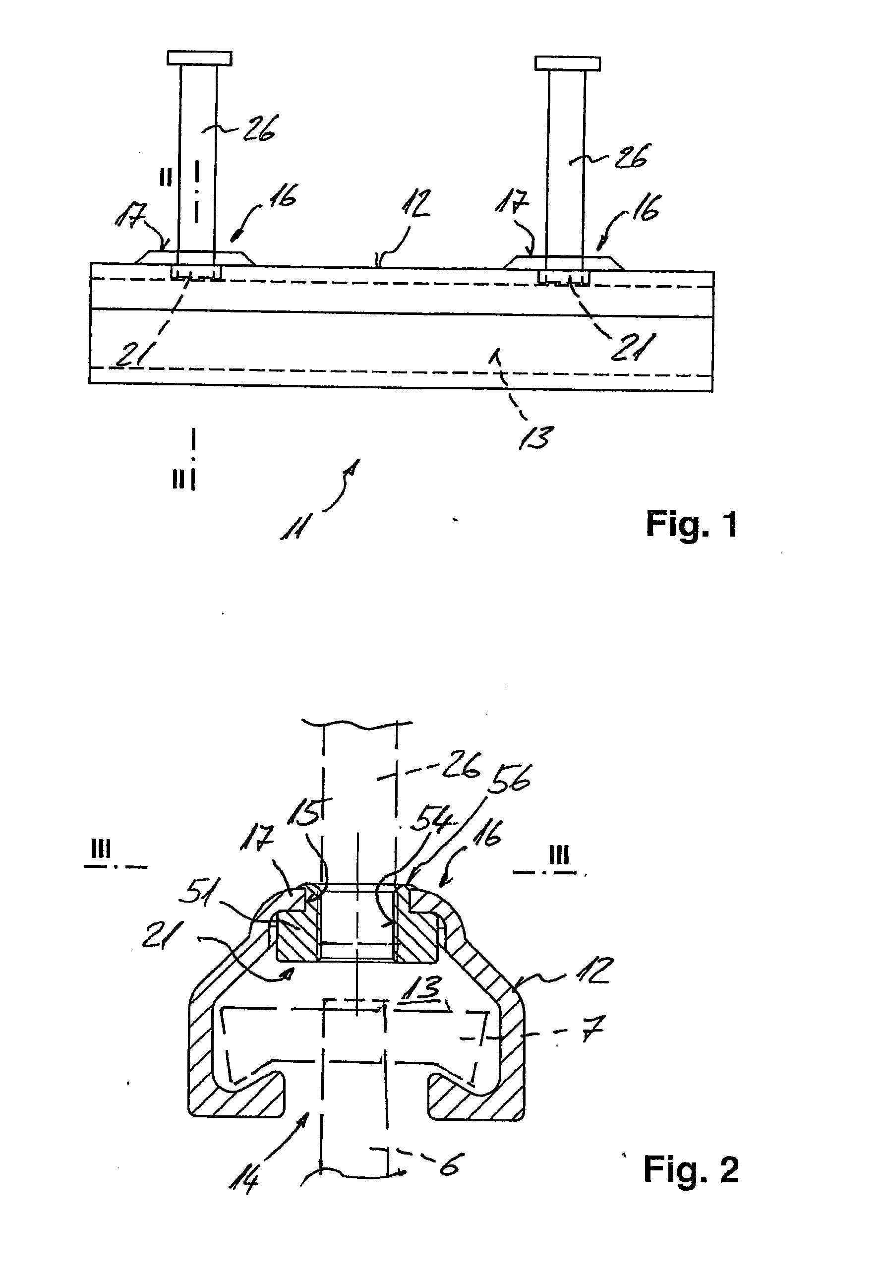
[0014]In an alternative embodiment, the fixing portion of at least one rivet grips around the edge of the hole from the inside relative to the receiving space, so that the fixing portion of the rivet is inserted through the hole from the outside, and is then expanded on the inside. In
spite of the installed connector, the remaining portion of the receiving space is sufficient to allow easy installation of the connecting element, even in small-sized channel bodies. In addition, the rivets can be easily brought to the channel body from the outside.
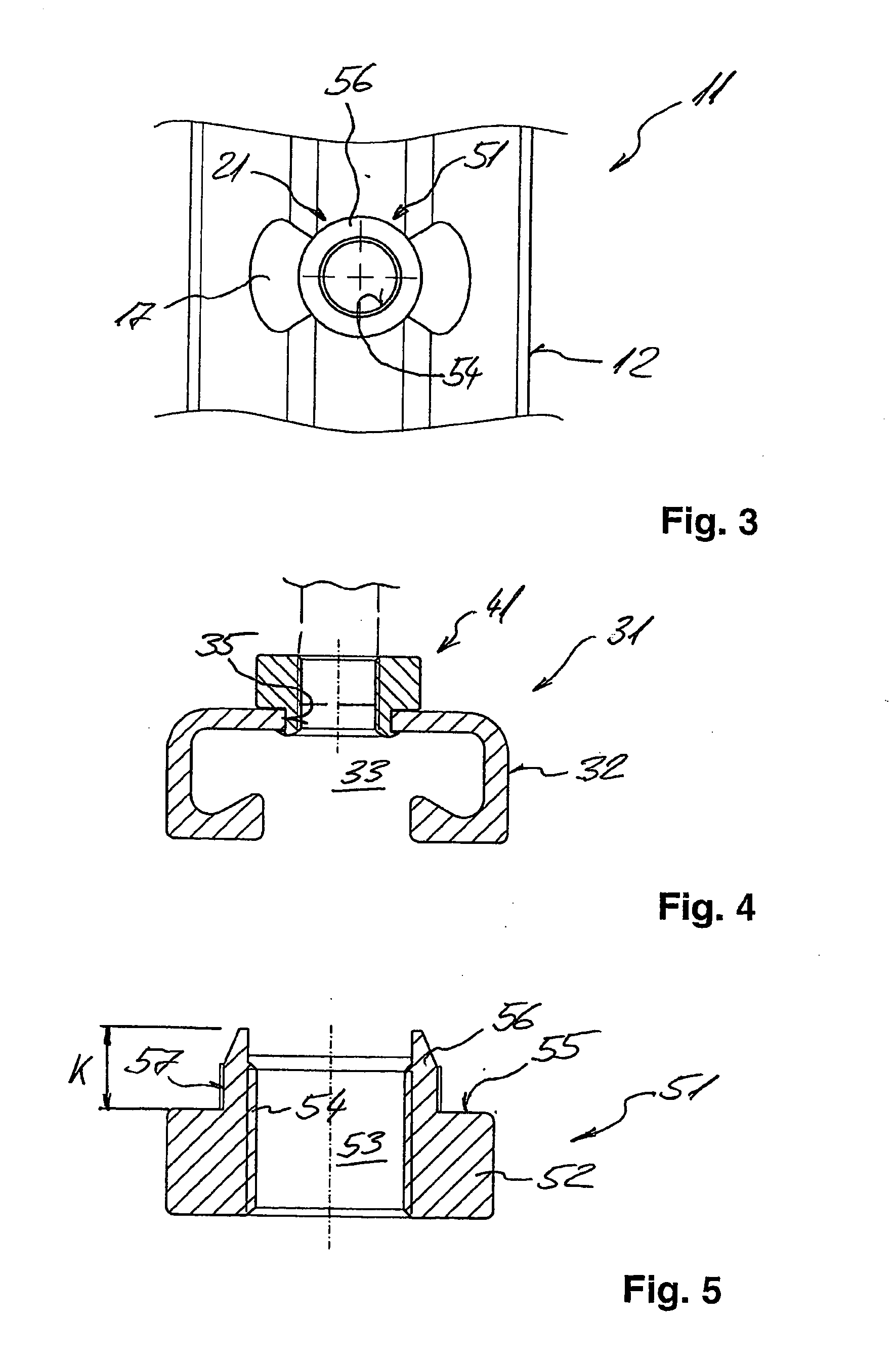
[0016]Preferably, at least one depression having a bottom portion is provided in the channel body, and at least one of the rivets is located in the bottom portion of the depression. For example, the at least one depression may be provided in the channel body such that it faces outwardly with respect to the receiving space, so that a depression which is cup-shaped, for example, creates additional mounting space for receiving a portion of a rivet, without said rivet portion reducing the mounting space for the connecting element within the receiving space. Advantageously, the rivet located in the bottom portion is oriented with respect thereto so that the attachment means of the rivet projects perpendicularly from the bottom portion. The bottom portion of the at least one depression may be non-concentric in cross section with respect to the rivet located therein. This allows the depression to be adapted according to the loading of the cast-in channel, for example. The bottom portion may be of elliptical or polygonal, such as rectangular configuration. The bottom portion does not have to be minor-symmetrical with respect to the hole located therein. Further, the bottom portion may be circular in cross section, and its center may be offset from the center of the rivet. The bottom portion of the at least one depression is provided with reinforcing indentations, for example, thereby advantageously strengthening this region of the depression and imparting advantageous load-carrying characteristics to the cast-in channel. By providing the depression in the channel body, this portion is work-hardened, so that the material of the channel body has a higher strength in this highly stressed region.
[0019]A rivet nut according to the present invention for a cast-in channel as mentioned above includes a main body and a collar portion as a fixing portion, said collar portion extending from the main body and being able to be expanded, in particular to be crimped over, the main body having a hole with an internally threaded portion for fixedly attaching the anchoring members, the internally threaded portion extending from the main body into the collar portion. This makes it possible to provide a greater number of thread turns than in a rivet nut that has an internally threaded portion only in the region of the main body. The greater grip length at the rivet nut allows greater loads to be transferred to the base material, whereby the load-
carrying capacity of the cast-in channel can be ensured while reducing the amount of material required to manufacture the same. Moreover, because the rivet nut has an internally threaded portion longer than that of conventional rivet nuts, it can be reduced in height and yet have the same load-
carrying capacity. This is beneficial especially when the rivet nut is arranged in the receiving space in such a manner that the fixing portion of the rivet grips around the edge of the hole from the outside.
[0020]Unlike an insert nut, a rivet nut allows the
free edge of a hole made in a corrosion-protected channel body to be protected from corrosion in a reliable and simple manner. In the case of an insert nut, which may also form a connector for fixedly attaching the anchoring members to the channel body, the side of the (mostly hardened) free end bites into the edge of the hole, but does not wrap completely around it, so that the edge is not protected from corrosion in simple way. Thus, an insert nut does not have a fixing portion that could be expanded or, in particular, crimped over.

