Plasma enhanced booster and method of operation

a booster and plasma technology, applied in the field of boosters, can solve the problems of reducing the backbone stiffness of the engine, high efficiency loss, and difficulty in maintaining the desired clearance over the rotor tips,

Inactive Publication Date: 2010-07-08
GENERAL ELECTRIC CO
View PDF34 Cites 43 Cited by
  • Summary
  • Abstract
  • Description
  • Claims
  • Application Information

AI Technical Summary

Problems solved by technology

Conventional transition or gooseneck duct geometries are governed by their levels of endwall curvature, since excessive curvature leads to endwall boundary layer separation and therefore high losses in efficiency.
This is not desirable because increased transition duct lengths translate directly to increased engine length, which in turn adds engine weight and reduces backbone stiffness of the engine.
This reduction in stiffness makes it more difficult to maintain the desired clearances over the rotor tips, reducing the efficiency and operability range of the engine.
As compressor and booster rotors approach the limits of their capability to add work / pressure to the air, they tend to become less efficient and, if pushed beyond this limit, stall (fail to produce their required pressure rise, leading to reversed flow through the stage and a loss of engine thrust).
A booster rotor that is designed very near to its limits in the rear stages of the booster could experience significant operability problems.
This is a concern in conventional booster system designs which are limited to lower radii in the aft rotor stages.

Method used


Image

  • Plasma enhanced booster and method of operation
  • Plasma enhanced booster and method of operation
  • Plasma enhanced booster and method of operation

Examples


Embodiment Construction

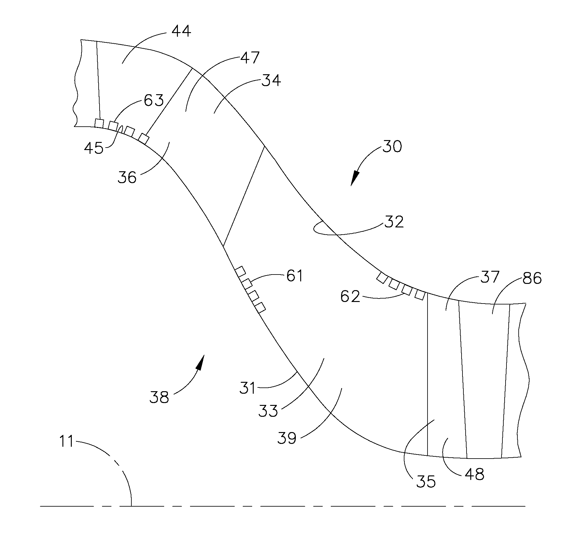
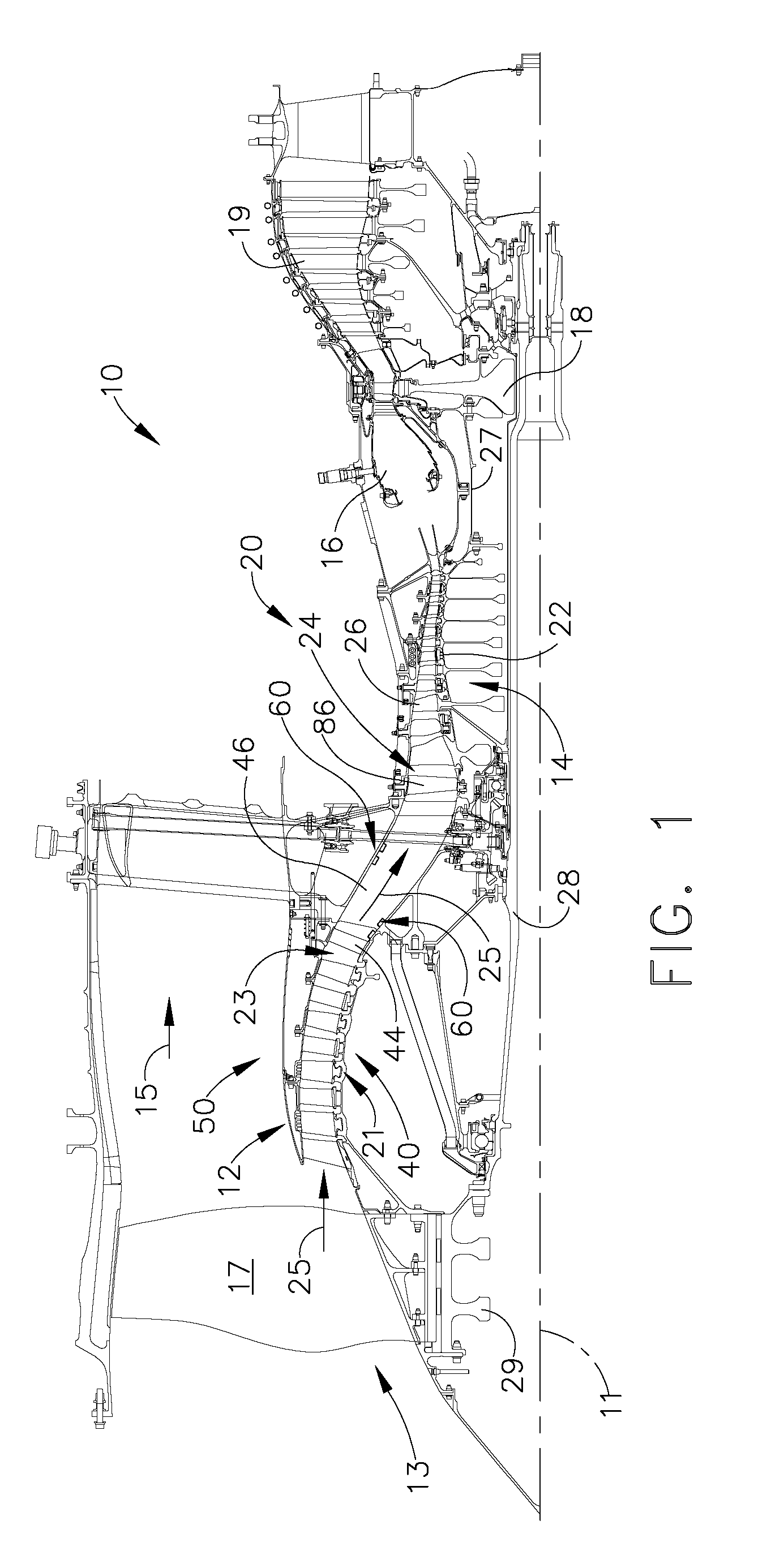
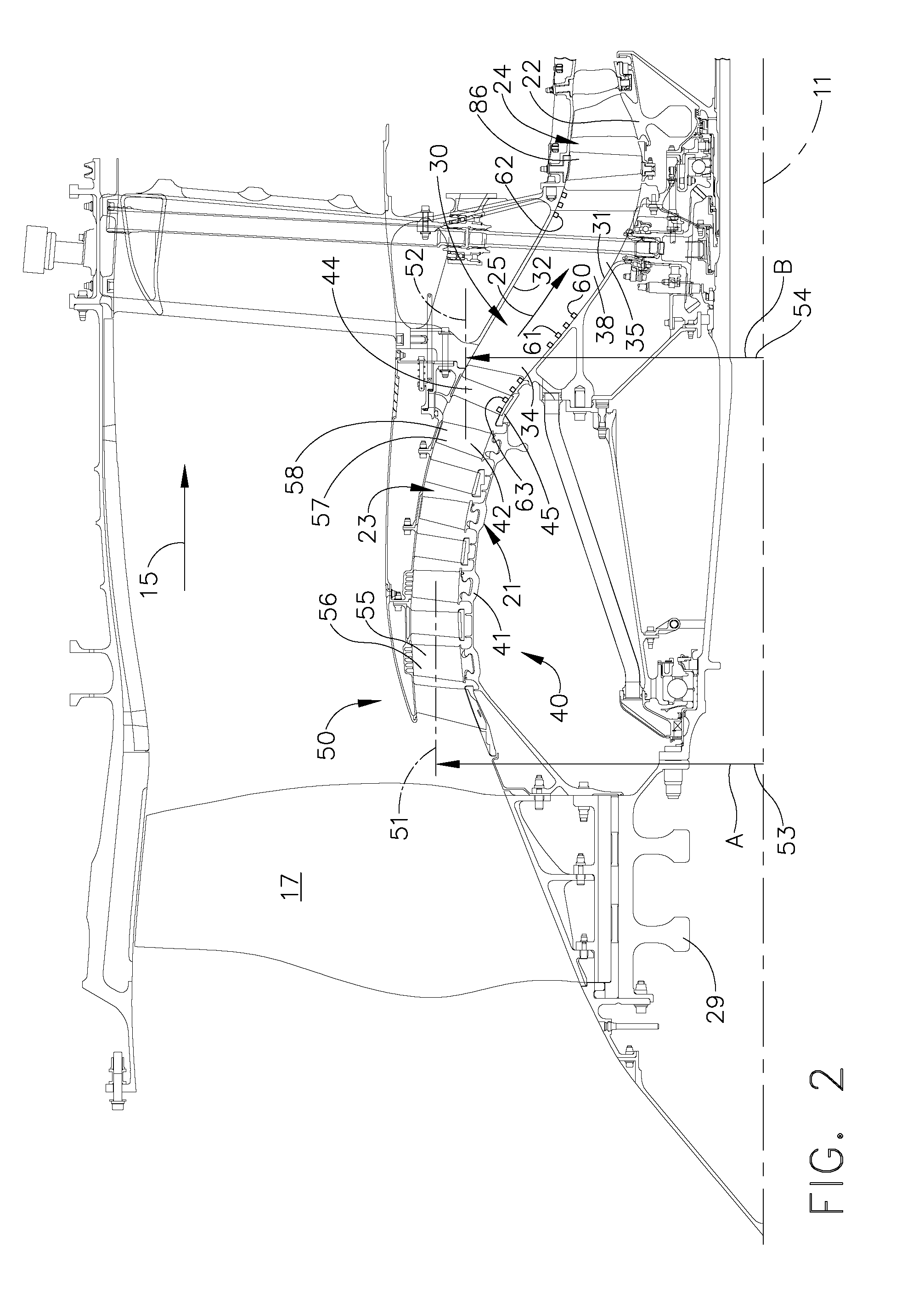
[0019]Referring to the drawings wherein identical reference numerals denote the same elements throughout the various views, FIG. 1 shows a cross-sectional view of an exemplary gas turbine engine assembly 10 having a longitudinal axis 11 and a compression system 20 comprising a first compressor 21 and a second compressor 22 that is located axially aft from the first compressor 21. In the exemplary embodiment shown in FIG. 1, the first compressor 21 is a booster 40, that is also referred to alternatively herein as a low-pressure compressor. The exemplary booster 40 shown in FIGS. 1 and 2 has four rotor stages, with each rotor stage having between 50 and 90 booster rotor blades. The exemplary booster system 50 has a row of stator vanes (alternatively referred to herein as booster inlet guide vanes “IGV”) located axially forward from the first booster rotor stage. The exemplary booster system 50 has a row of stator vanes (alternatively referred to herein as booster outlet guide vanes 44...


PUM


Abstract

A booster system is disclosed, comprising a first rotor stage having a plurality of first rotor blades spaced circumferentially around a rotor hub with a longitudinal axis and having a first pitch-line radius extending from the longitudinal axis, a last rotor stage located axially aft from the first rotor stage, the last rotor stage comprising a plurality of last rotor blades spaced circumferentially around the longitudinal axis and having a second pitch-line radius extending from the longitudinal axis, and a gooseneck duct located axially aft from the last rotor stage and capable of receiving an airflow, the gooseneck duct comprising an inlet end and an exit end located at a distance axially aft from the inlet end and having at least one plasma actuator mounted in the gooseneck duct.

Description

BACKGROUND OF THE INVENTION[0001]This invention relates generally to compressors, and more specifically to a booster system having a transition duct having plasma actuators.[0002]In a gas turbine engine, air is pressurized in a compression module during operation. The air channeled through the compression module is mixed with fuel in a combustor and ignited, generating hot combustion gases which flow through turbine stages that extract energy therefrom for powering the fan and compressor rotors and generate engine thrust to propel an aircraft in flight or to power a load, such as an electrical generator.[0003]The compressor includes a rotor assembly and a stator assembly. The rotor assembly includes a plurality of rotor blades extending radially outward from a disk. More specifically, each rotor blade extends radially between a platform adjacent the disk, to a tip. A gas flowpath through the rotor assembly is bound radially inward by the rotor blade platforms, and radially outward b...

Claims


Application Information

Patent Timeline
Patent Type & Authority Applications(United States)
IPC IPC(8): F02K3/04
CPCF01D5/143F01D5/145F01D9/04F05D2270/17F05D2270/172Y02T50/671Y02T50/673Y02T50/675F05D2260/221F04D29/687Y02T50/60
Inventor CLARK, DAVID SCOTTWADIA, ASPI RUSTOMLEE, CHING PANGWOOD, PETER JOHN
Owner GENERAL ELECTRIC CO
Why Eureka
Try Eureka