Late lean injection with expanded fuel flexibility

a technology of flexible fuel and lean injection, which is applied in the direction of combustion control, machines/engines, lighting and heating apparatus, etc., can solve the problems of significant nox formation, high nox formation, and gas turbine engine failure to operate at high efficiencies

Active Publication Date: 2010-07-08
GENERAL ELECTRIC CO
View PDF35 Cites 53 Cited by
  • Summary
  • Abstract
  • Description
  • Claims
  • Application Information

AI Technical Summary

Problems solved by technology

Currently, some gas turbine engines fail to operate at high efficiencies and produce undesirable air polluting emissions.
However, it has been seen that, for heavy duty industrial gas turbines, even with the use of premixed lean fuels, the required temperatures of the combustion products are so high that the combustor must be operated with peak gas temperatures in the reaction zone that exceed the thermal NOx formation threshold temperature, resulting in significant NOx formation.

Method used


Image

  • Late lean injection with expanded fuel flexibility
  • Late lean injection with expanded fuel flexibility
  • Late lean injection with expanded fuel flexibility

Examples


Embodiment Construction

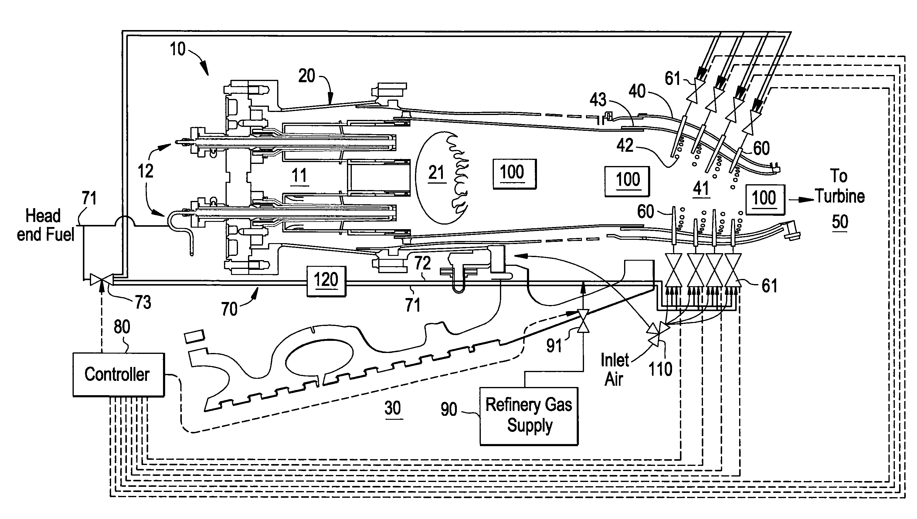
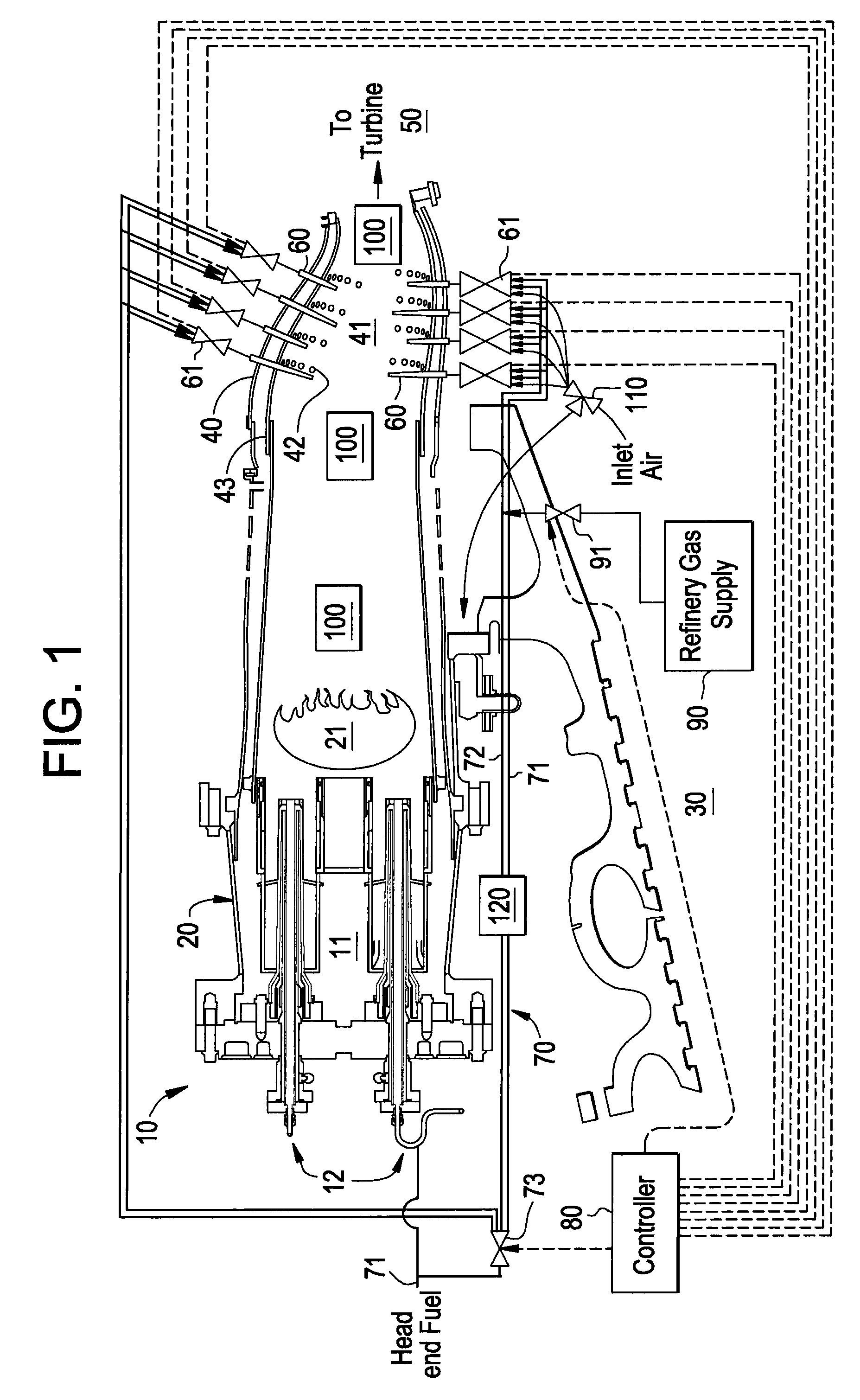
[0015]With reference to FIG. 1, a gas turbine engine 10 is provided and includes a combustor 20 having a first interior 21 in which a first fuel supplied thereto by fuel circuit 70 is combustible, a compressor 30 by which inlet air is compressed and provided to at least the combustor 20 and a transition zone 43 and a turbine 50, including rotating turbine blades, into which products of at least the combustion of the first fuel are receivable to power a rotation of the turbine blades. The transition zone 43 is disposed to fluidly couple the combustor 20 and the turbine 50 and includes a second interior 41 in which a second fuel supplied thereto by the fuel circuit 70 and the products of the combustion of the first fuel are combustible. As shown, the combustor 20 and the transition zone 43 combine with one another to generally have a form of a head end 11, which may have various configurations, as will be discussed below.

[0016]As shown in FIG. 1, the head end 11 may include multiple p...


PUM


Abstract

A gas turbine engine is provided and includes a fuel circuit, including multiple fuel circuit branches, a combustor having a first interior in which a first fuel supplied thereto by any one of the multiple fuel circuit branches is combustible, a turbine, a transition zone, including a second interior in which a second fuel supplied thereto by any one of the multiple fuel circuit branches, the second fuel including gas receivable by the fuel circuit from an external source, and the products of the combustion of the first fuel are combustible, the transition zone being disposed to fluidly couple the combustor and the turbine to one another, and a plurality of fuel injectors which supply the second fuel to the second interior in any one of a single axial stage, multiple axial stages, a single axial circumferential stage and multiple axial circumferential stages.

Description

CROSS REFERENCE TO RELATED APPLICATIONS[0001]This Application is related to the following applications: “Late Lean Injection Fuel Staging Configurations”; “Late Lean Injection System Configuration”; “Late Lean Injection Fuel Injector Configurations”; “Late Lean Injection with Adjustable Air Splits”; “Late Lean Injection for Fuel Flexibility” and “Late Lean Injection Control Strategy”, each of which is being filed concurrently herewith and the contents of which are incorporated herein by reference thereto.BACKGROUND OF THE INVENTION[0002]Aspects of the present invention are directed to late lean injection (LLI) fuel staging configurations and methods of achieving the same.[0003]Currently, some gas turbine engines fail to operate at high efficiencies and produce undesirable air polluting emissions. The primary air polluting emissions usually produced by turbines burning conventional hydrocarbon fuels are oxides of nitrogen, carbon monoxide and unburned hydrocarbons. To this end, since...

Claims


Application Information

Patent Timeline
Patent Type & Authority Applications(United States)
IPC IPC(8): F02C7/22F02C7/00F02C3/04
CPCF02C7/228F23C2900/07021F23N1/002F23N2025/08F23N2037/08F23N2041/20F23R3/286F23R3/346F23R3/36F23R3/40F23R2900/00002F23N2225/08F23N2237/08F23N2241/20
Inventor DAVIS, JR., LEWIS BERKLEYVENKATARAMAN, KRISHNA KUMARZIMINSKY, WILLY STEVETERRY, JASON CHARLES
Owner GENERAL ELECTRIC CO
Why Eureka
Try Eureka