Refrigerating and air conditioning apparatus

a technology for refrigerating and air conditioning equipment, applied in the direction of defrosting, separation process, domestic cooling equipment, etc., can solve problems such as discomfort and growth

Inactive Publication Date: 2010-07-08
MITSUBISHI ELECTRIC CORP
View PDF0 Cites 20 Cited by
  • Summary
  • Abstract
  • Description
  • Claims
  • Application Information

AI Technical Summary

Benefits of technology

[0014]With the refrigerating and air conditioning apparatus according to the present invention, in the refrigerating and air conditioning apparatus having a refrigeration circuit in which refrigerant is put and provided with a compressor for compressing the refrigerant, condenser, throttle device, and evaporator, and water adsorption means which adsorbs water in the air-conditioned space to release it outside, since an adsorbent is employed whose time constant of water adsorption equilibrium becomes small as the wind velocity increases, it becomes possible to change dehumidification capability and latent heat capability by changing the wind velocity, so that load following capability is enhanced and reliability of the refrigerating and air conditioning apparatus is improved.

Problems solved by technology

Resultantly, a state occurs that the evaporating temperature increases to remove a sensible heat of a room, however, no latent heat is removed, so that a relative humidity of the room increases to cause discomfort to grow.

Method used


Image

  • Refrigerating and air conditioning apparatus
  • Refrigerating and air conditioning apparatus
  • Refrigerating and air conditioning apparatus

Examples


Embodiment Construction

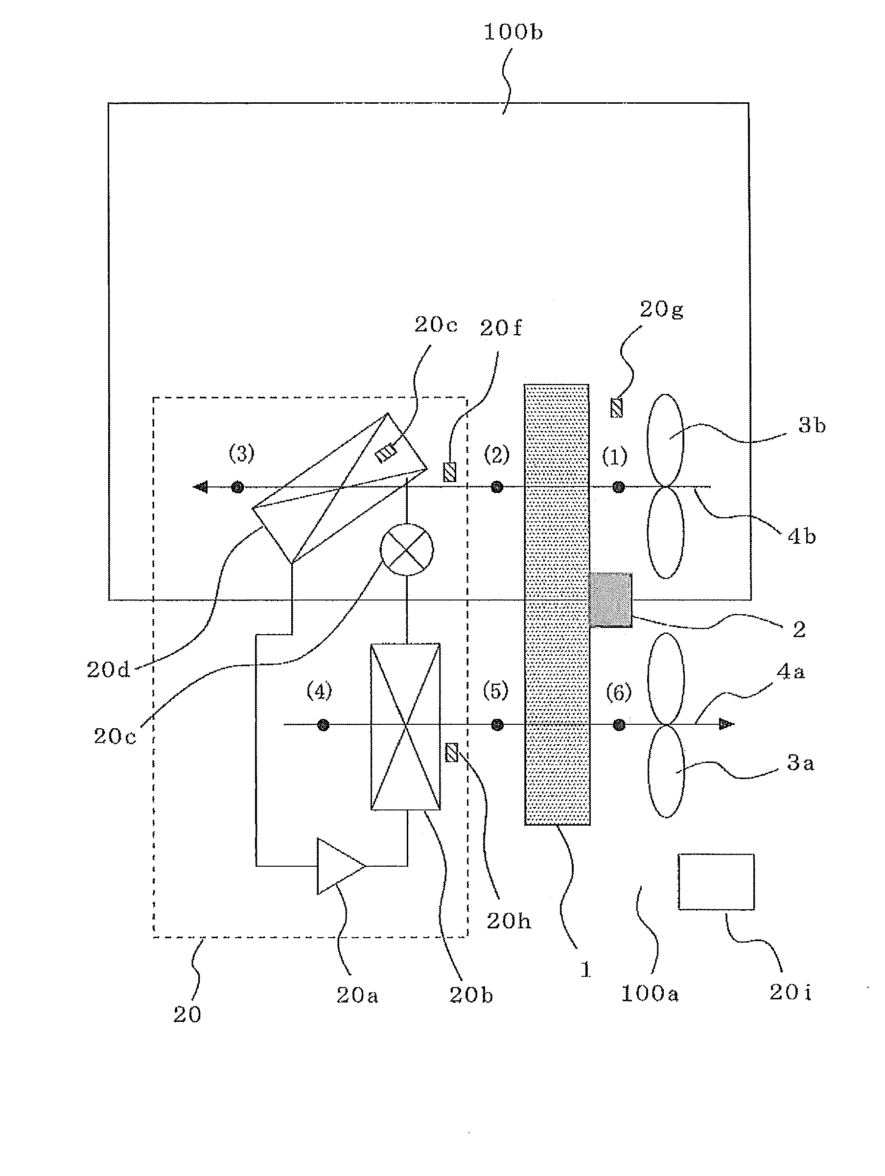
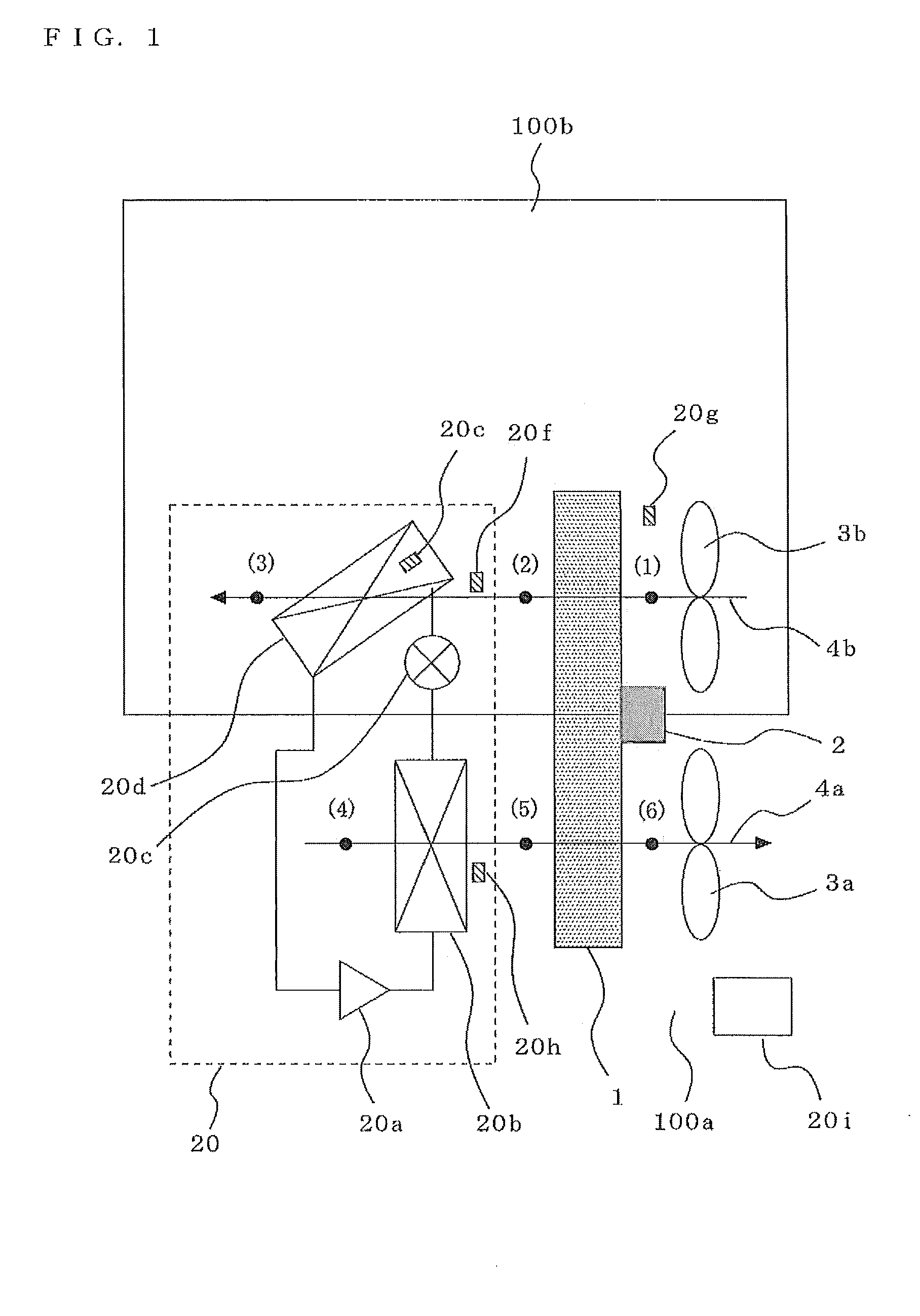
[0055]Descriptions will be given to the refrigerating and air conditioning apparatus according to the present embodiment. In FIG. 1, the refrigerating and air conditioning apparatus is provided with water adsorption means and refrigerator 20. In addition to a desiccant rotor 1, which is water adsorption means; motor, which is driving means 2 for driving the desiccant rotor 1; fan 3a for supplying a first air 4a to the desiccant rotor 1, which is the air of an open air side 100a; and fan 3b for supplying a second air 4b to the desiccant rotor 1, which is the air in a refrigeration room 100b, R404A, HFC system refrigerant, is sealed, and the apparatus is composed of the refrigerator 20 including a compressor 20a, condenser 20b, expansion valve 20, which is a throttle device, and evaporator 20d. The refrigerant can be R134a, R407c, R41aA, ammonia, BC, and so on. Since CO2 is refrigerant operating at a critical point and over, its characteristic is that a high air temperature is easily ...


PUM


Abstract

In a range of a wind velocity of 0.5 to 3.5 (m/s) in a refrigeration cycle, when combining absorbent having a small dependency on the wind velocity and the refrigeration cycle, it is not possible to vary dehumidification capability by changing the wind velocity and matching with an actual load is poor. In a refrigerating and air conditioning apparatus having a refrigerator 20 in which refrigerant is put, and having a compressor 20a for compressing the refrigerant, a condenser 20b, and a throttle device 20c, and an evaporator 20d, and a desiccant rotor 1, which is water adsorption means, an adsorbent is supported with the desiccant rotor 1, whose time constant at a water adsorption equilibrium becomes small as a wind velocity increases in the range of the wind velocity of 0.5 to 3.5 m/s, the condenser 20b is disposed upwind of the desiccant rotor 1, and the evaporator 20d is disposed downwind of the desiccant rotor 1.

Description

TECHNICAL FIELD[0001]The present invention relates to a refrigerating and air conditioning apparatus combining a desiccant and steam compression refrigerating cycle, and more particularly to improvement of a load following capability by combining an adsorbent having an excellent matching especially with a refrigeration cycle.BACKGROUND ART[0002]A conventional refrigerating and air conditioning apparatus having a dehumidification function is composed of a compressor, a condenser, an expansion valve, an evaporator, and a defrost heater. In a refrigeration cycle of the refrigerating and air conditioning apparatus, refrigerant is put. The refrigerant compressed by the compressor turns into a high-temperature high-pressure gas refrigerant to be supplied to the condenser. The refrigerant flowing into the condenser is liquefied by releasing heat into the air. The liquefied refrigerant is decompressed by the expansion valve to be turned into a gas-liquid two-phase state and gasified by abso...

Claims


Application Information

Patent Timeline
Patent Type & Authority Applications(United States)
IPC IPC(8): F25B49/00F25B1/00F25D17/06F25D21/00
CPCB01D53/06B01D53/261B01D53/265F24F3/1423F24F2203/1016F24F2203/1068F24F2203/1084
Inventor MORIMOTO, HIROYUKISUGIMOTO, TAKESHIMATSUOKA, FUMIOYAMASHITA, KOJIYAMASHITA, TETSUYAFUKUI, KOUJIMAEGAWA, TAKEYUKI
Owner MITSUBISHI ELECTRIC CORP
Why Eureka
Try Eureka