
Integrated electric compressor

a compressor and electric technology, applied in the direction of machines/engines, liquid fuel engines, lighting and heating apparatus, etc., can solve the problems of insufficient solution, large size of packaging parts, and virtually increasing thickness of control boards

Active Publication Date: 2010-07-08
MITSUBISHI HEAVY IND LTD
View PDF3 Cites 12 Cited by
  • Summary
  • Abstract
  • Description
  • Claims
  • Application Information

AI Technical Summary

Benefits of technology

[0017]The voltage application wiring pattern and the output wiring pattern are high-voltage systems in which a high voltage, such as 300 V, flows, and the signal line pattern is a low-voltage system in which a low voltage, such as 5 V, flows. The high-voltage systems and the low-voltage system are disposed so as to be opposed to each other, with the switching element interposed, whereby it is possible to prevent electromagnetic noise caused by the high-voltage systems from having an affect on a signal of the low-voltage system.
[0019]According to the present invention, the miniaturization of the first board can be accomplished by performing the bare-chip assembly of the IGBT and the diode on the first board. This enables the region where the IGBT and the diode are provided to be made small and it becomes possible to dispose the IGBT and the diode in the region along the surface of the housing that is cooled by the flow of the refrigerant in the housing. As a result, it becomes possible to miniaturize the control board while ensuring a layout in which the heat radiation of parts is considered.

Problems solved by technology

However, when package parts are used in the switching elements as previously, the package parts have sizes that are large to a certain degree.
In this concept, however, the thickness of the control board increases virtually and, therefore, it cannot be said that this is an adequate solution from the standpoint of miniaturization.
However, because the arrangement of the parts is limited by this, it is difficult to miniaturize the control board also in this respect.

Method used


Image

  • Integrated electric compressor
  • Integrated electric compressor
  • Integrated electric compressor

Examples


Embodiment Construction

[0028]The present invention will be described below in detail on the basis of an embodiment shown in the accompanying drawings.

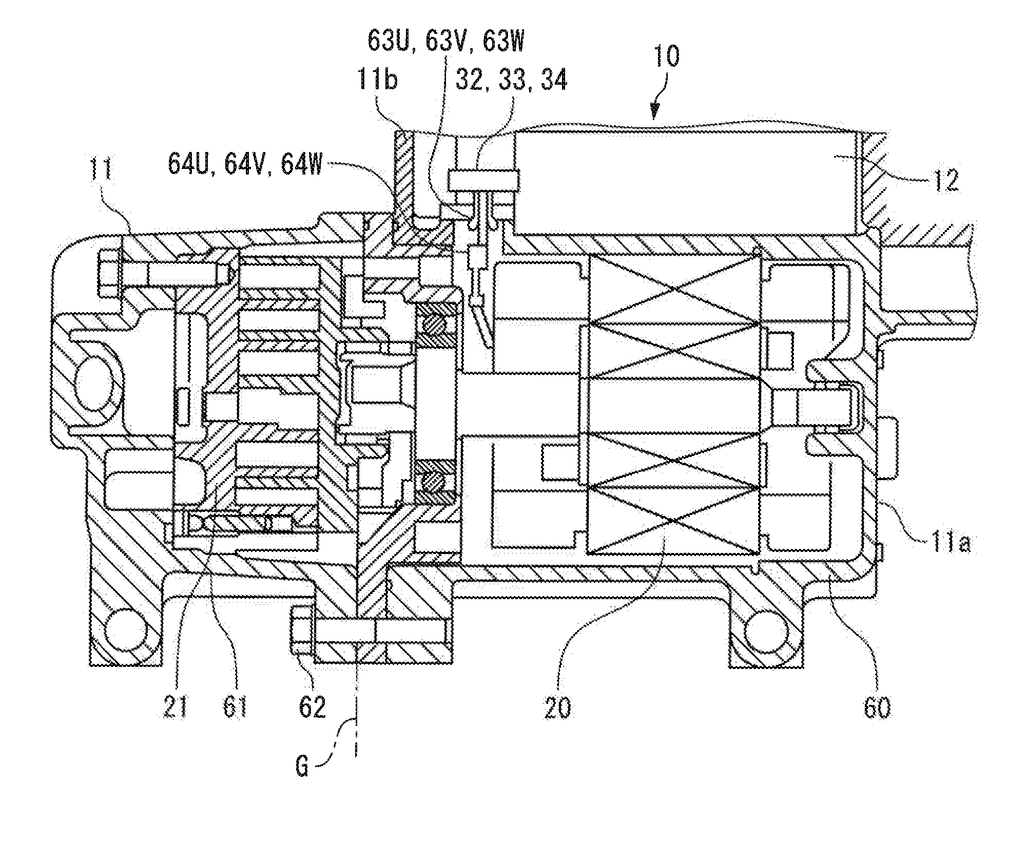
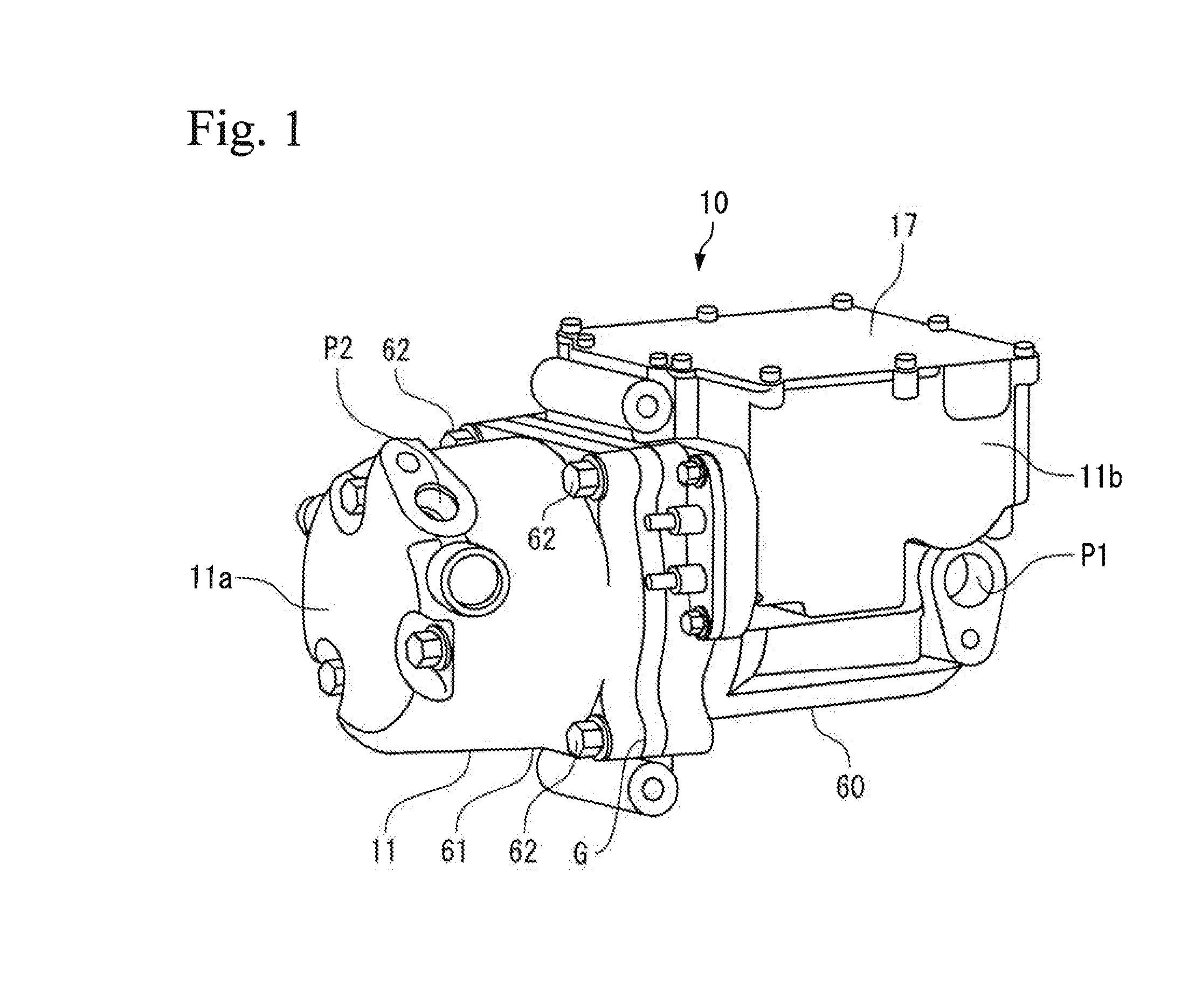
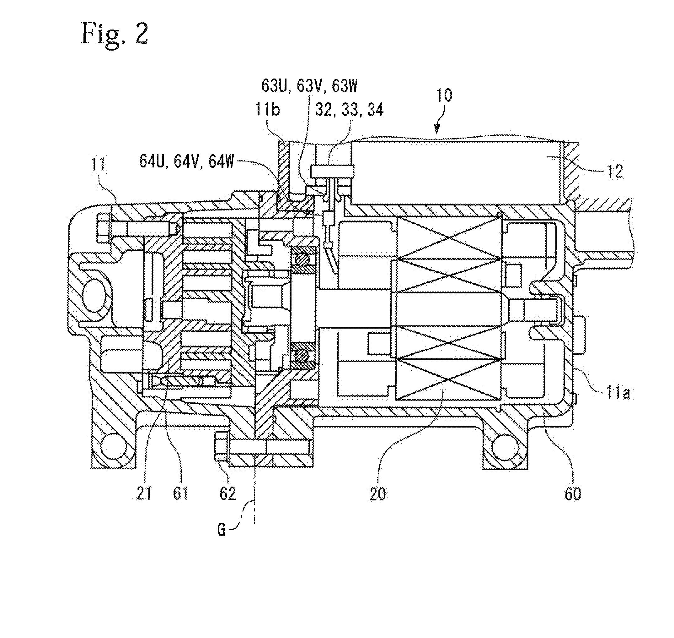
[0029]FIGS. 1 and 2 are diagrams to show the construction of an electric compressor (an integrated electric compressor) 10 in this embodiment.

[0030]As shown in FIGS. 1 and 2, the electric compressor 10 is such that a motor 20 and a scroll-type compressor 21 are housed in a lower housing chamber 11a of a housing 11. An inverter unit 12 is housed in an upper housing chamber 11b of the housing 11 that opens upward. An upward opening of the upper housing chamber 11b is covered with a cover 17.

[0031]As shown in FIG. 1, a refrigerant is introduced into the housing 11 from a refrigerant introduction port P1, which is formed in an end portion of the lower housing chamber 11a on the side where the motor 20 is provided, and the refrigerant compressed by the compressor 21 is discharged from a refrigerant discharge port P2, which is formed in an end portion on the side ...


PUM


Abstract

The object is to provide an integrated compressor that enables a control board to be miniaturized while ensuring a layout in which the heat radiation of parts is considered. Diodes 43 and IGBTs 42 that correspond to each of the U-phase, V-phase and W-phase are arrayed in series for each phase. Rectangular chips are used for the diodes 43 and IGBTs 42. As a result of this, a power board 16 is substantially miniaturized, and the diode 43, the IGBT 42, a P-terminal electrode pattern 40, an N-terminal electrode pattern 41, a shunt resistor 44, output terminal patterns 48U, 48V, 48W, and a feed pattern 50 are disposed so as to lie in a region in contact with an outer surface of a housing.

Description

TECHNICAL FIELD[0001]The present invention relates to an integrated electric compressor that constitutes a vehicle-mounted air conditioner.BACKGROUND ART[0002]A vehicle-mounted air conditioner is required to meet space savings because various pieces of equipment are housed in the engine room of a vehicle. For this reason, in recent years there have been provided integrated electric compressors in which a compressor that constitutes a vehicle-mounted air conditioner, a motor for driving the compressor and a driving board for driving the motor are housed integrally in a housing.[0003]In such an integrated electric compressor, switching elements composed of a plurality of IGBTs (insulated gate bipolar transistors) are provided on a board for controlling the operation of a motor in order to supply a three-phase alternating current to the motor. A high voltage, such as 300 V, is supplied to these switching elements from an external high-voltage power source (not shown) (refer to Patent D...

Claims


Application Information

Patent Timeline
IPC IPC(8): F25B31/00F04C18/02F04C28/00
CPCF04C18/0215F04C23/008F04C2240/803F04C2240/808H01L25/162H01L2924/0002H01L2924/00H02K11/33
Inventor NAKAGAMI, TAKASHINAKANO, KOJIASAI, MASAHIKOHATTORI, MAKOTONIWA, KAZUKI
Owner MITSUBISHI HEAVY IND LTD
Learn More