Illuminant device

a technology of illumination device and lid plate, which is applied in the direction of lighting support device, display means, instruments, etc., can solve the problems of increasing the cost of illuminant device increasing the manufacturing cost of lid plate, etc., so as to improve the workability of mounting the substrate, simplify the structure of the substrate, and prevent the effect of outside dus

Inactive Publication Date: 2010-07-08
SHARP KK
View PDF5 Cites 63 Cited by
  • Summary
  • Abstract
  • Description
  • Claims
  • Application Information

AI Technical Summary

Benefits of technology

[0047]In this invention, since a recess space can be created inside the frame body, a substrate such as an inverter substrate to be connected to the lamps can be mounted on the frame body apart from the plate body, the structure for mounting the substrate can be simplified, and the workability for mounting the substrate can be improved.
[0048]According to the present invention, the end parts of the juxtaposed plate bodies are superposed on each other, and thereby outside dust can be prevented from entering the chassis from a clearance between the end parts of the plate bodies.
[0049]According to the present invention, the end parts of the juxtaposed chassis components are superposed on each other, and thereby outside dust can be prevented from entering the chassis from a clearance between the end parts of the chassis components.
[0050]According to the present invention, the end parts of the plate bodies or t

Problems solved by technology

However, since the lid plate of the chassis in the illuminant device is formed from a metal plate and the lid plate is formed by a die, a super-sized die for forming a lid-plate is required for an illuminant device to be used for a comparatively large-sized display device, the cost regarding manufacturing efficiency of the lid plate and a lid-plate manufacturing equipment increases, the manufacturing cost of the lid plate and accordingly, the cost of the illuminant device increase, and hence improvement is required.
Moreover, there is a problem that the lid plate expands thermally with heat generated by the lamp etc. and a curve, deflection and deformation occur in said lid plate easily.
However, in the illuminant device, since end parts of the adjacent plate bodies oppose to each other, and the connecting members connect the end parts of the adjacent plate bodies in this state, it is likely to generate a clearance between the end parts of the adjacent

Method used


Image

  • Illuminant device
  • Illuminant device
  • Illuminant device

Examples


embodiment 1

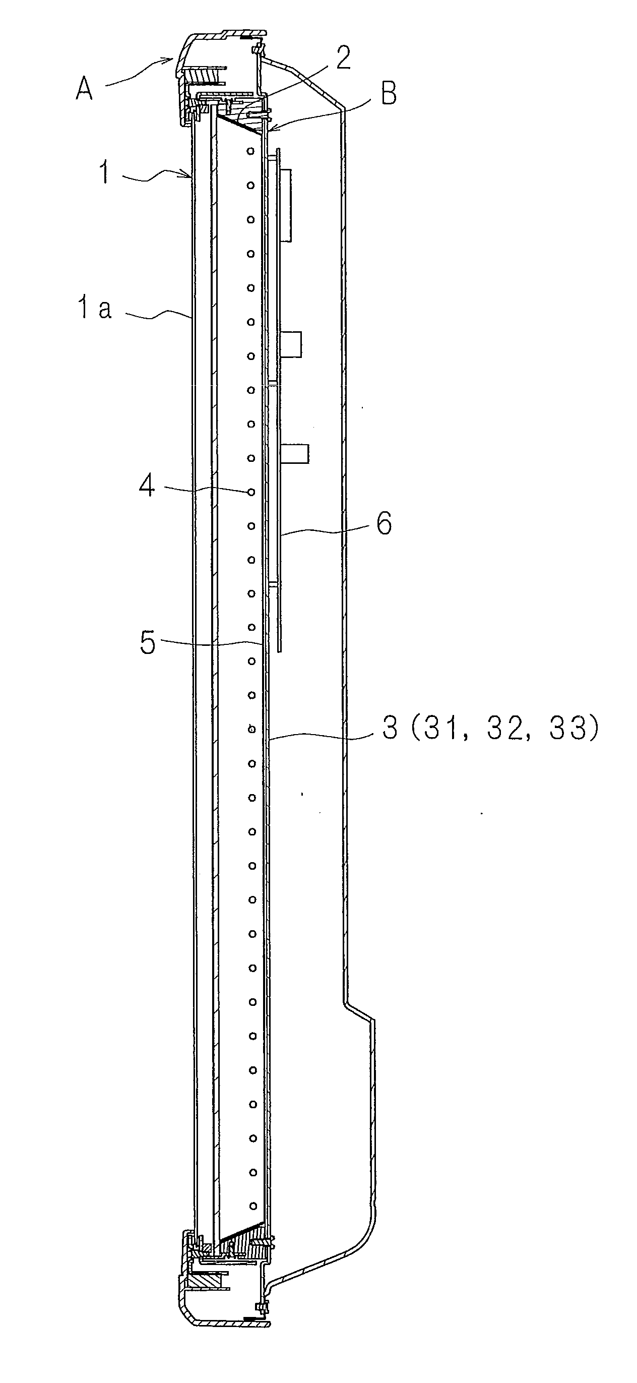
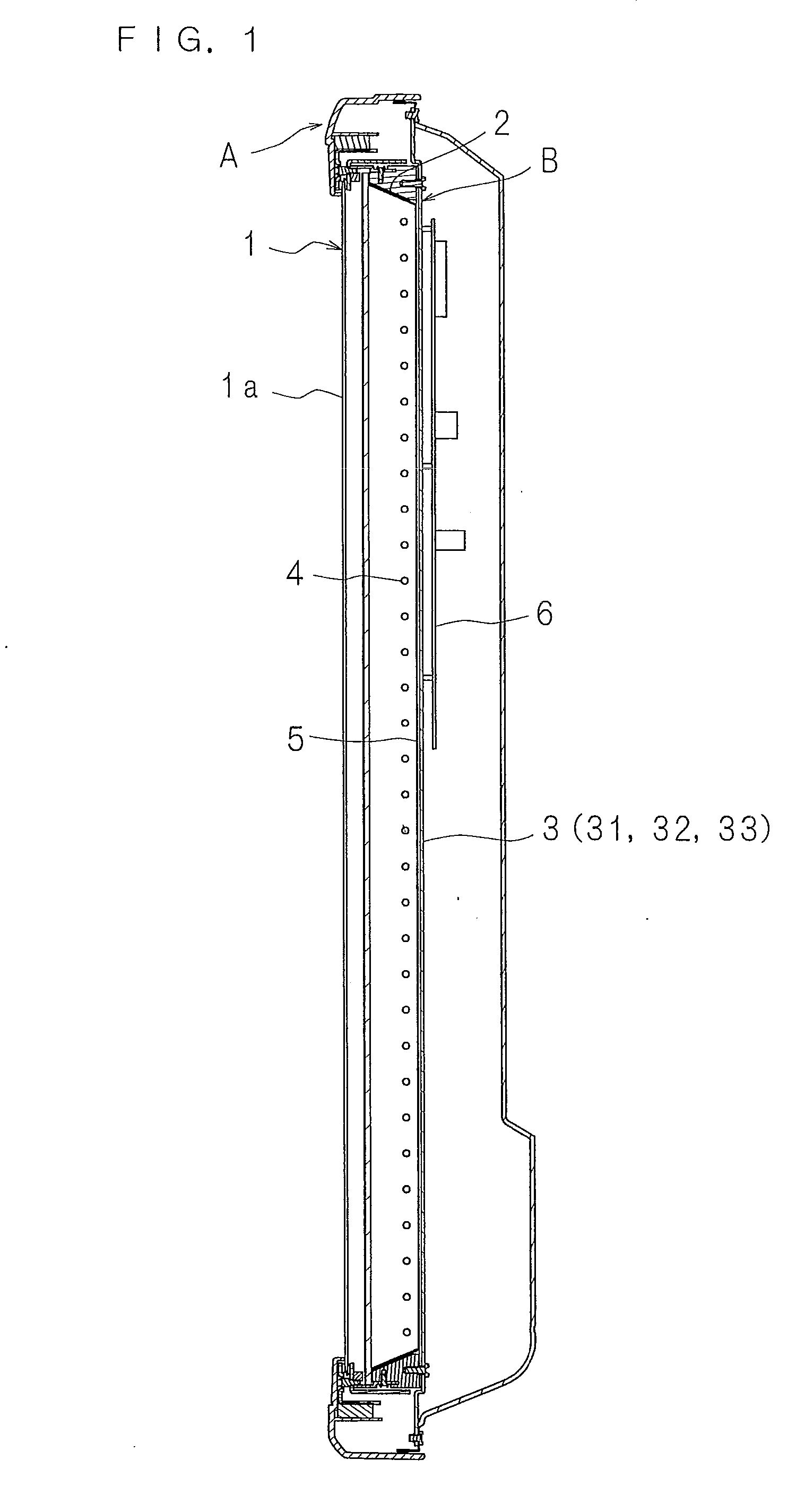
[0084]FIG. 1 is a sectional view showing a configuration of an illuminant device according to the present invention incorporated in a display device, FIG. 2 is a rear view showing a configuration of a chassis of an illuminant device according to the present invention, FIG. 3 is an exploded perspective view showing a configuration of the chassis in which a frame part is omitted, FIG. 4 is an enlarged sectional view taken along line IV-IV in FIG. 2, and FIG. 5 is an enlarged sectional view where a part of the line IV-IV in FIG. 2 is omitted.

[0085]The illustrated illuminant device is mounted behind a display unit 1 in a thin display device A provided with the display unit 1 having a display surface 1a on a front side thereof and an approximately rectangular parallelepiped shape. The illuminant device comprises a chassis B having a frame part 2 and a lid plate 3 and having a box shape with a front side thereof opened, a plurality of lamps 4 which have straight tubular shapes and are jux...

embodiment 2

[0097]FIG. 6 is an enlarged sectional view showing a main part in another configuration of the chassis of the illuminant device, and FIG. 7 is an exploded enlarged perspective view showing a main part in another configuration of the chassis. In the illuminant device, instead of using the connecting unit 7 having the strip-shaped plates 71 like Embodiment 1, concave parts 31e, 33g which are depressed in the superposed direction are provided in the superposed end parts 31c, 33c of the first and third plate bodies 31, 33, at a plurality of positions disposed with a distance therebetween in the direction in which the plate bodies 31 to 33 are juxtaposed, concave parts 32e, 33h which are depressed in the superposed direction are provided in the superposed end parts 32c, 33c of the second and third plate bodies 32, 33, at a plurality of positions disposed with a distance therebetween in the direction in which the plate bodies 31 to 33 are juxtaposed, through holes 31f, 33i, 32f, 33j penet...

embodiment 3

[0100]FIG. 8 is an enlarged sectional view showing a main part in another configuration of the chassis of the illuminant device. In this illuminant device, instead of the concave parts 31e, 33g and the concave parts 32e, 33h provided in the superposed end parts 31c, 33b and the superposed end parts 32c, 33c, respectively, like Embodiment 2, the concave parts 33g, 33h are provided in the end parts 33b, 33c of the third plate body 33, through holes 33k, 33m penetrating in said superposed direction are perforated at a plurality of positions in a longitudinal direction of the concave parts 33g, 33h, and cylindrical bodies 34 (or cylinder parts) projecting in the superposed direction and arranged in the concave parts 33g, 33h are provided in the end parts 31c, 32c of the first and second plate bodies 31, 32. Then the male screws 72 are inserted into the through holes 33k, 33m, and are screwed into the cylindrical bodies 34, thereby connecting the superposed end parts 31c, 33b and the sup...


PUM


Abstract

In a chassis which has a lid plate closing an opening portion of a frame part and in which a plurality of lamps are juxtaposed, the lid plate includes a plurality of plate bodies juxtaposed with their end parts superposed on each other and a connecting unit connects the superposed end parts of the plate bodies and the superposed end parts of the plate bodies, respectively.

Description

[0001]This application is the national phase under 35 U.S.C. §371 of PCT International Application No. PCT / JP2008 / 059907 which has an International filing date of May 29, 2008 and designated the United States of America.BACKGROUND[0002]1. Technical Field[0003]The present invention relates to an illuminant device to be used as a light source of a display device such as a liquid crystal display device.[0004]2. Description of Related Art[0005]In the display device such as a television, an illuminant device is arranged behind a display unit having a display surface which displays an image on a front side thereof.[0006]The illuminant device comprises, for example, a plurality of lamps having electrodes in both end parts thereof, and a chassis which includes a frame part having a rectangular parallelepiped shape, a lid plate closing an opening portion of the frame part, and a plurality of reinforcement crosspieces mounted to the lid plate with a distance therebetween, and in the chassis, ...

Claims


Application Information

Patent Timeline
IPC IPC(8): F21V7/04
CPCG02F1/133308G02F1/133608G02F2201/503G02F2001/133314G02F2001/133328G02F2001/133311G02F1/133311G02F1/133314G02F1/133328
Inventor TAKEUCHI, HIDETOFUJIWARA, KOUICHITOYAMA, AKIRA
Owner SHARP KK
Why Eureka
Try Eureka