
Methods and apparatus for reducing nozzle stress

a stress reduction and nozzle technology, applied in the direction of machines/engines, forging/pressing/hammering apparatus, liquid fuel engines, etc., can solve the problems of reducing the useful and the life of the nozzle trailing edge, so as to facilitate the reduction of stress and reduce the effect of stress

Active Publication Date: 2010-07-08
GENERAL ELECTRIC CO
View PDF10 Cites 10 Cited by
  • Summary
  • Abstract
  • Description
  • Claims
  • Application Information

AI Technical Summary

Benefits of technology

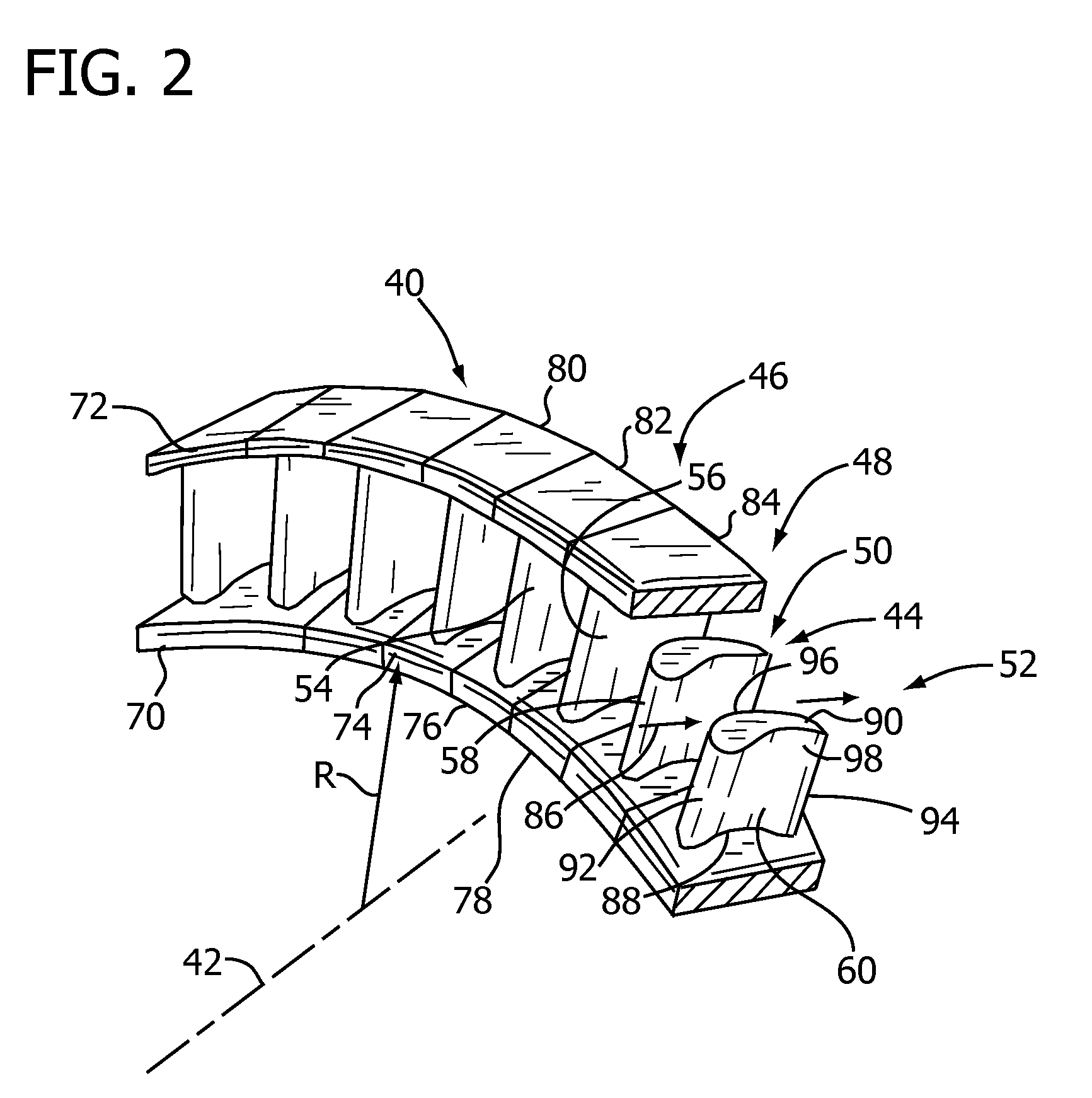
[0004]In one aspect, a gas turbine engine nozzle is provided. The nozzle includes at least one nozzle vane including a first end and a second end. The first end is coupled to an inner sidewall and the second end is coupled to an outer sidewall. The nozzle also includes at least one stress relief pocket defined within at least one of the inner sidewall and the outer sidewall and proximate to the at least one nozzle vane. The at least one stress relief pocket facilitates reducing stress induced to said nozzle vane.
[0005]In another aspect, a gas turbine engine including at least one turbine stage is provided. The at least one turbine stage includes a plurality of turbine blades and a nozzle set positioned upstream from the plurality of turbine blades. The nozzle set is configured to channel airflow downstream to the turbine blades. The nozzle set includes at least one stress relief pocket configured to reduce stresses induced to the nozzle set.
[0006]In yet another aspect, a method for reducing nozzle stress is provided. The method includes providing a plurality of nozzles, each nozzle including an inner sidewall and an outer sidewall, and at least one nozzle vane that extends therebetween. At least one of the plurality of nozzles includes at least one stress relief pocket defined within at least one of the inner sidewall and the outer sidewall. The method also includes positioning the plurality of nozzles to form an annular nozzle set.

Problems solved by technology

Typically, a useful life of a nozzle is limited to the life of the nozzle trailing edge.
For example, exposure to changing temperatures, in combination with the varying thickness of each nozzle, causes strain on the nozzle that may reduce a useful life of the nozzle.

Method used


Image

  • Methods and apparatus for reducing nozzle stress
  • Methods and apparatus for reducing nozzle stress
  • Methods and apparatus for reducing nozzle stress

Examples


Embodiment Construction

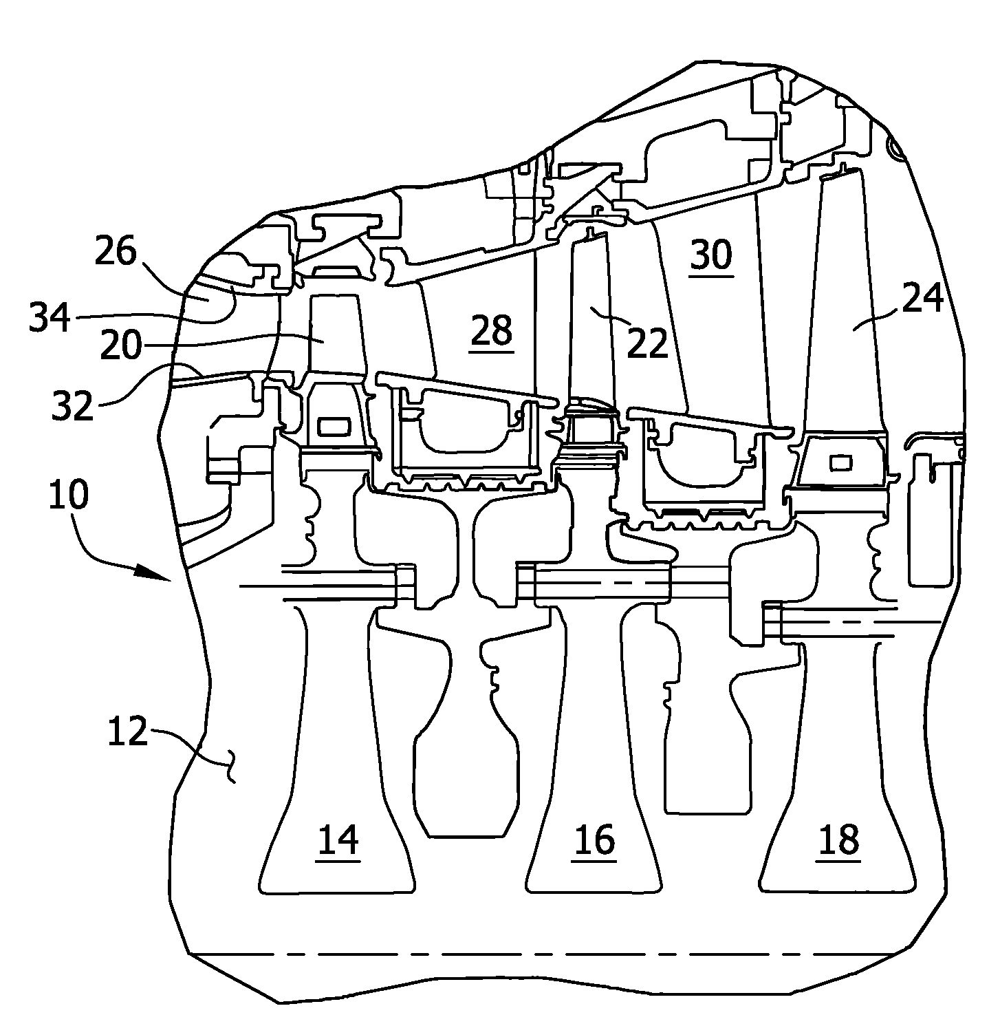
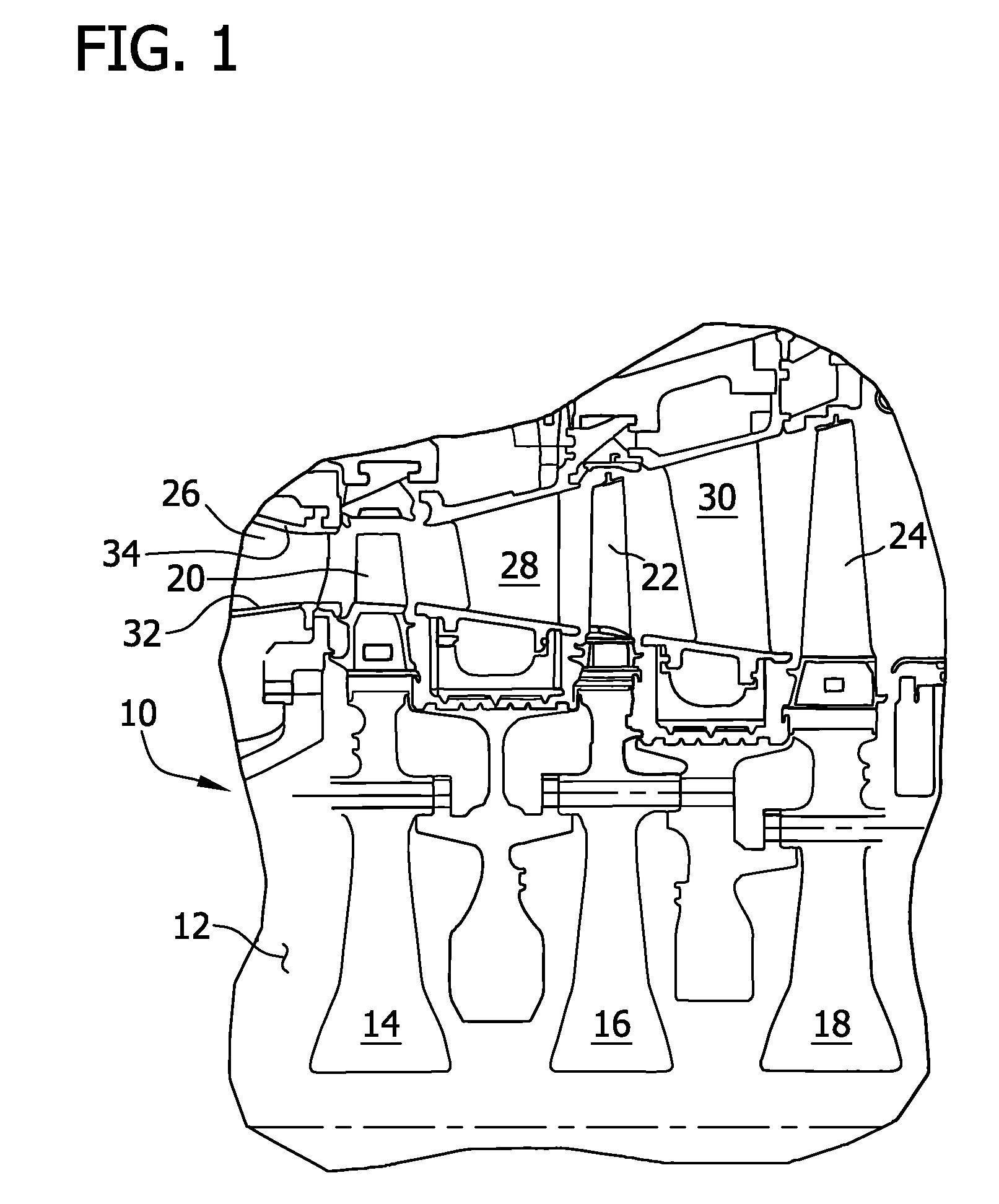
[0013]FIG. 1 illustrates a cross-sectional view of an exemplary turbine 10. In the exemplary embodiment, turbine 10 includes a rotor 12 having respective first, second, and third stage rotor wheels 14, 16, and 18 that include respective buckets 20, 22, and 24 and respective nozzles 26, 28, and 30. Each row of buckets 20, 22, and 24 and nozzles 26, 28, and 30, defines a subsequent stage of turbine 10. In the exemplary embodiment, turbine 10 is a three stage turbine. Alternatively, turbine 10 may include more or less than three stages. In one embodiment, turbine 10 is a General Electric 7FA+e gas turbine, manufactured by General Electric Company of Schenectady, N.Y.

[0014]Within the first turbine stage, a plurality of buckets, including bucket 20, are spaced circumferentially about first stage rotor wheel 14. The plurality of buckets, including bucket 20, are mounted in axial opposition to an upstream nozzle set, which includes nozzle 26. The plurality of nozzles, including nozzle 26, ...


PUM

PropertyMeasurementUnit
stressaaaaaaaaaa
shapeaaaaaaaaaa
cross-sectional shapeaaaaaaaaaa

Abstract

A gas turbine engine nozzle is described. The gas turbine engine nozzle includes at least one nozzle vane having a first end and a second end. The first end is coupled to an inner sidewall and the second end is coupled to an outer sidewall. The gas turbine engine nozzle also includes at least one stress relief pocket defined within at least one of the inner sidewall and the outer sidewall proximate to the at least one nozzle vane. The at least one stress relief pocket is configured to reduce stress on the proximate nozzle vane.

Description

BACKGROUND OF THE INVENTION[0001]The field of the disclosure relates generally to gas turbine engines, and more specifically, to methods and apparatus for reducing nozzle stress in a gas turbine engine.[0002]A gas turbine engine generally includes in serial flow communication a compressor, a combustor, and a turbine. The compressor provides compressed airflow to the combustor wherein the airflow is mixed with fuel and ignited, which creates combustion gases. The combustion gases flow to the turbine which extracts energy therefrom.[0003]The turbine includes one or more stages, with each stage having an annular turbine nozzle set for channeling the combustion gases to a plurality of rotor blades. The turbine nozzle set includes a plurality of circumferentially spaced nozzles fixedly joined at their roots and tips to a radially inner sidewall and a radially outer sidewall, respectively. Each individual nozzle has an airfoil cross-section and includes a leading edge, a trailing edge, an...

Claims


Application Information

Patent Timeline
Patent Type & Authority Applications(United States)
IPC IPC(8): F01D9/02B23P11/00
CPCF01D9/02Y10T29/49323F05D2240/122F05D2260/941
Inventor SNOOK, DANIEL DAVIDBENJAMIN, EDWARD DURELL
Owner GENERAL ELECTRIC CO
Learn More