Method For Prediction In An Oil/Gas Production System

a technology of oil/gas production system and prediction method, which is applied in the direction of instruments, separation processes, and well accessories, etc., can solve the problems of reducing throughput, increasing the cost of multi-rate well testing, and reducing the reliability of the system, so as to reduce the uncertainty

Inactive Publication Date: 2010-07-08
ABB AS
View PDF3 Cites 42 Cited by
  • Summary
  • Abstract
  • Description
  • Claims
  • Application Information

AI Technical Summary

Benefits of technology

[0025]Instead of requiring a series of designed experiments in the form of e.g. multi-rate well tests for each well as disclosed in the prior art, the inventive method is preferably designed to exploit variation observed during normal operations. To account for the fac...

Problems solved by technology

As production may require a time to settle once manipulated variables are changed, multi-rate well tests require a well to be routed to a test separator for a longer duration and may therefore be more costly.
As the production system may already be producing at the constraints of its processing capacities, care must be taken not to exceed these constraints when a multi-rate well test is performed, so that multi-rate well tests have a risk and a possible cost related to temporary reduction in throughput.
Therefore, all wells in the system cannot continuously be monitored.
A drawback of predictions based on commercial simulators either directly or through proxy-models, is that some error in the ability of the model to predict responses in production to changes in manipulated variables must be expected due to the complexity of modeling multiphase flows.
The cost in terms of increased risk for complete or partial shut downs and/or temporarily reduced throughput of performing multi-rate well tests means that this is usually not a viable option.
Fitting model...

Method used


Image

  • Method For Prediction In An Oil/Gas Production System
  • Method For Prediction In An Oil/Gas Production System
  • Method For Prediction In An Oil/Gas Production System

Examples


Embodiment Construction

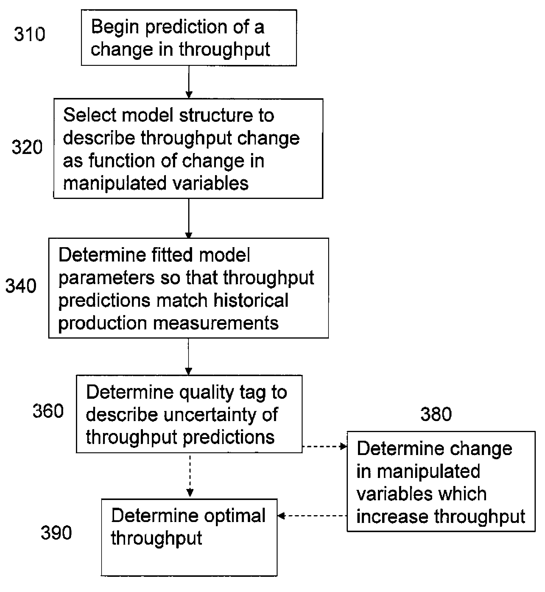
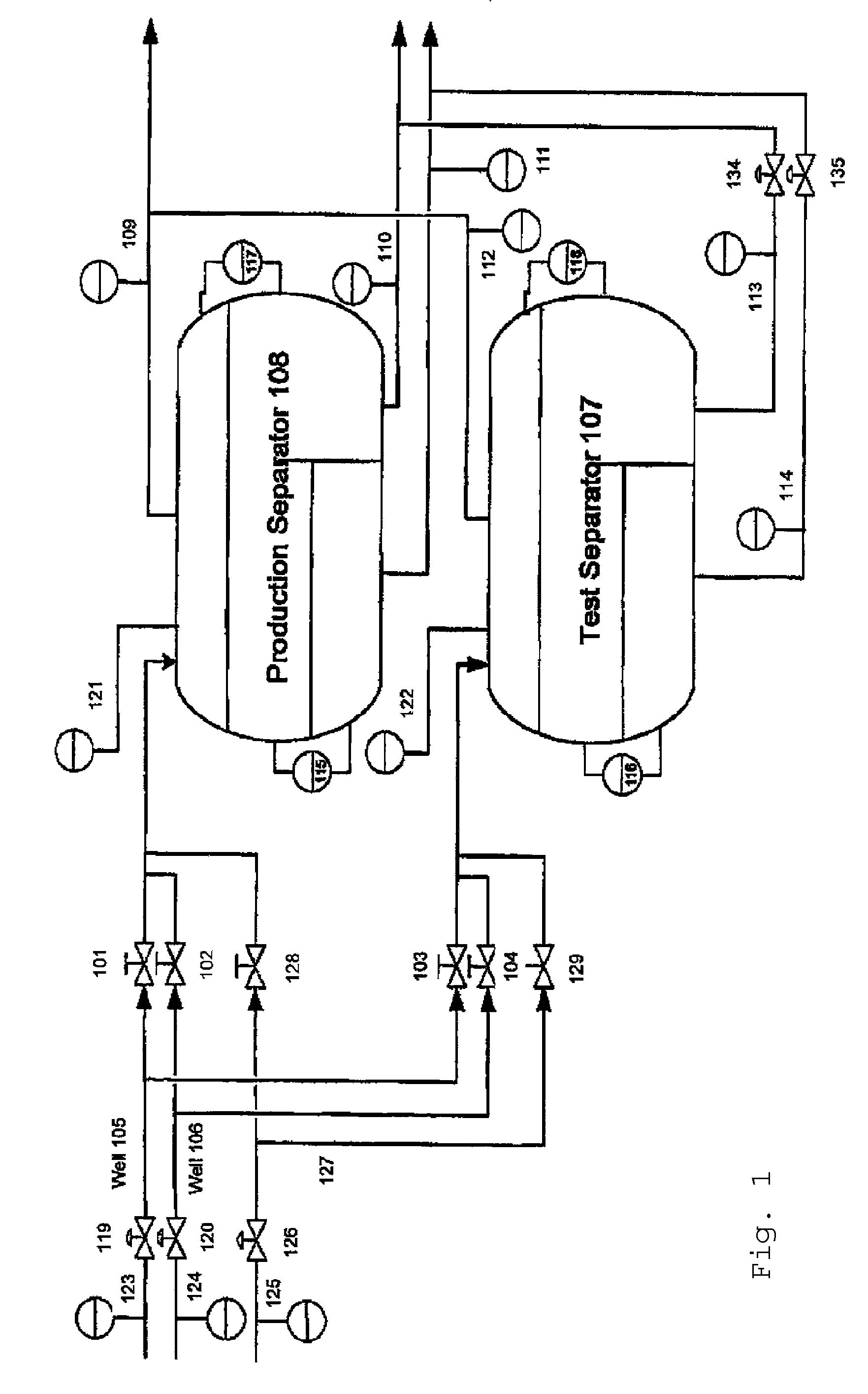
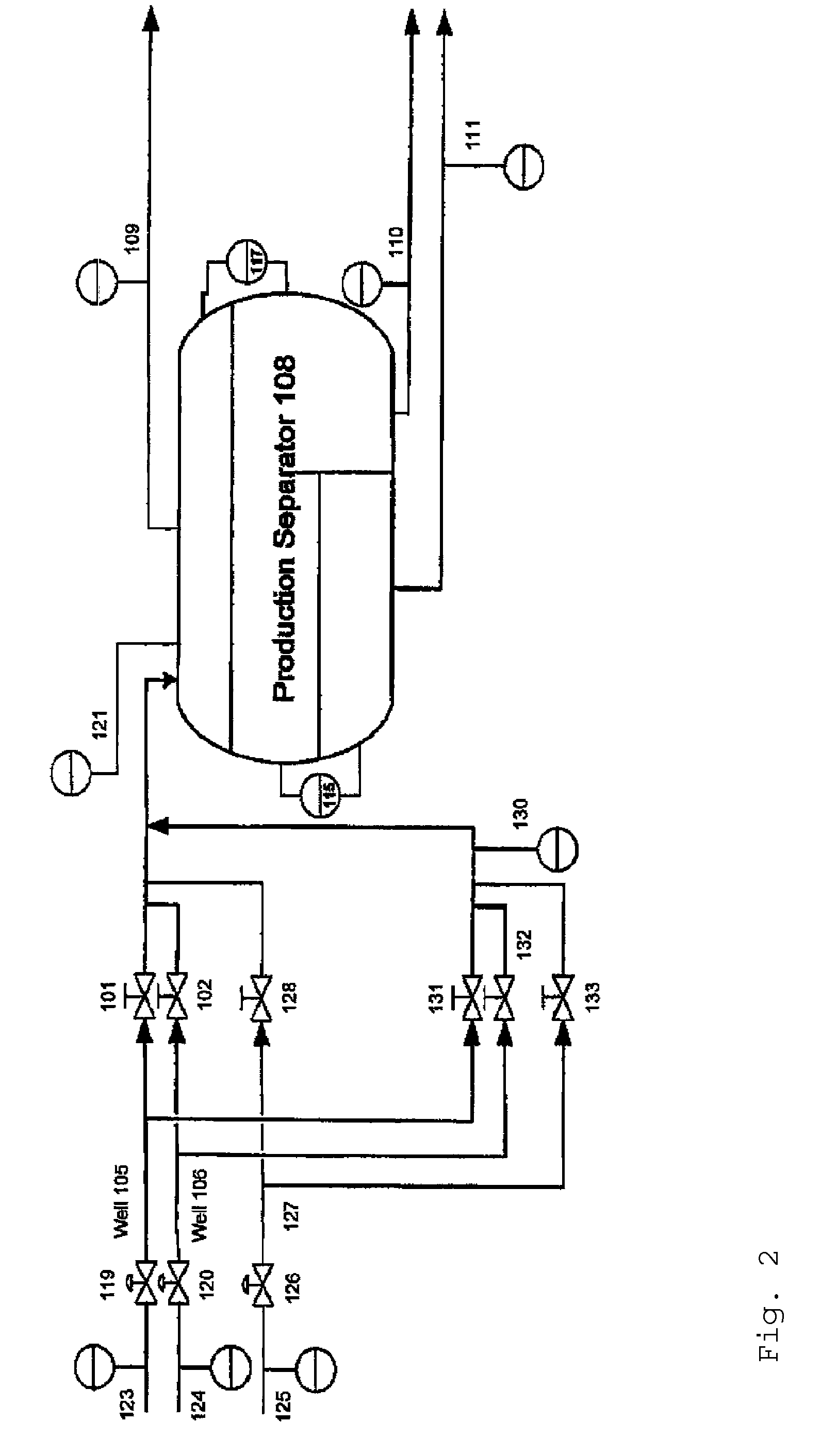
[0047]In FIG. 1 is shown a schematic drawing of an oil and or gas production system where the present invention may be applied.

[0048]The system comprises three wells 105, 106, 127, a production separator 108 and a test separator 107. The invention may naturally be also used in systems comprising two wells, or more than three wells.

[0049]123 designates an upstream valve pressure of a valve 119 of a well 105; 124 designates an upstream valve pressure of a valve 120 of a well 106, and 125 designates an upstream valve pressure of a valve 126 for well 127. The term valve should herein be understood in a broad sense, i.e. to include a choke, a gate valve, a routing valve or a control valve.

[0050]101, 102, 128 designate routing valves for production separator 108 for the wells 105, 106 and 127, respectively.

[0051]103, 104 and 129 designate routing valves for test separator 107 for the wells 105, 106 and 127, respectively.

[0052]109 designates a flow rate measurement device for gas of produc...


PUM


Abstract

Method in an oil and/or a gas production system including a plurality of oil and/or gas wells each producing a multiphase fluid stream, adapted for predicting change in produced fluids resulting from change in manipulated variables. Fitted model parameters which express the relationship between the change in manipulated variables and the produced fluids are determined from a set of historical production measurements. The method includes the steps of choosing a model structure which predicts change in produced fluids as a function of the change in manipulated variables, where the predicted change in produced fluids depends on the value of fitted model parameters, determining fitted model parameters so that predictions of produced fluids match said historical production measurements as closely as possible, and determining a quality tag that describes the uncertainty of the predictions of change in produced fluids.

Description

CROSS-REFERENCE TO RELATED APPLICATIONS[0001]The present application is a continuation of pending International patent application PCT / EP2008 / 061787 filed on Sep. 5, 2008, which designates the United States and claims priority from Norwegian patent application number 20074557 filed on Sep. 7, 2007, and claims the benefit under 35 U.S.C. §119(e) of the U.S. Provisional Patent Application Ser. No. 60 / 935,945 filed on Sep. 7, 2007. All prior applications are herein incorporated by reference in their entirety.FIELD OF THE INVENTION[0002]The present invention relates to a method in an oil and / or a gas production system comprising a plurality of oil and / or gas wells each producing a multiphase fluid stream, adapted for predicting change in produced fluids resulting from change in manipulated variables. The present invention also relates to a computer program product for executing one or more steps according to the method, and a system for an oil and / or a gas production in correspondence w...

Claims


Application Information

Patent Timeline
IPC IPC(8): G06G7/57
CPCE21B43/00E21B43/34G01F1/74B01D17/0211G01F25/0007B01D17/0208G01F15/068G01F25/10
Inventor SLUPPHAUG, OLAVELGSAETER, STEINAR
Owner ABB AS
Why Eureka
Try Eureka