Collision sensing device

a sensing device and collision technology, applied in the direction of force measurement by elastic gauge deformation, measurement/indication equipment, instruments, etc., can solve the problems of nozzle bending, damage to objects, and coating can only provide limited protection

Active Publication Date: 2010-07-15
WATER JET SWEDEN
View PDF8 Cites 2 Cited by
  • Summary
  • Abstract
  • Description
  • Claims
  • Application Information

AI Technical Summary

Benefits of technology

[0011]The deformable member is preferably a splatter shield which has the form of a frustum of a cone with circular cross-section. The cone is arranged with its wider end towards a workpiece. Hereby a relatively large detection or sensing area is obtained, within which a collision with one or more objects is detected. The splatter shield can also take other forms. The splatter shield can e.g. be of rectangular cross-section, or be tubular. The space that is assigned the pressure is defined by the upper side of the splatter shield, a bulge enclosing the upper side of the splatter shield and also a support plate which is sealingly arranged against the bulge. In this manner, a collision sensing device of simple construction in achieved.

Problems solved by technology

Such a coating can only provide a limited protection.
In case the nozzle is guided with great force, for instance, there is a risk that the nozzle is bent as a result of collision with an object.
Also the object may be may be damaged.
Further, U.S. Pat. No. 5,366,156 A does not provide for a detection of the collision.
Technique of this kind is relatively expensive.
Moreover, the sensors are sensitive to dirt, humidity and mechanical influences.
However, this solution has not led to satisfying results.
This is partly because these collisions sensing devises often have been damaged due to mechanical influences, and partly because they have been expensive owing to a relatively complex design construction.

Method used


Image

  • Collision sensing device
  • Collision sensing device
  • Collision sensing device

Examples


Embodiment Construction

[0016]Below, an embodiment of the invention is described with reference to the enclosed figures. The embodiment merely serves as an example of an application of the invention, and is not intended to limit the claimed scope, which is defined by the independent claims.

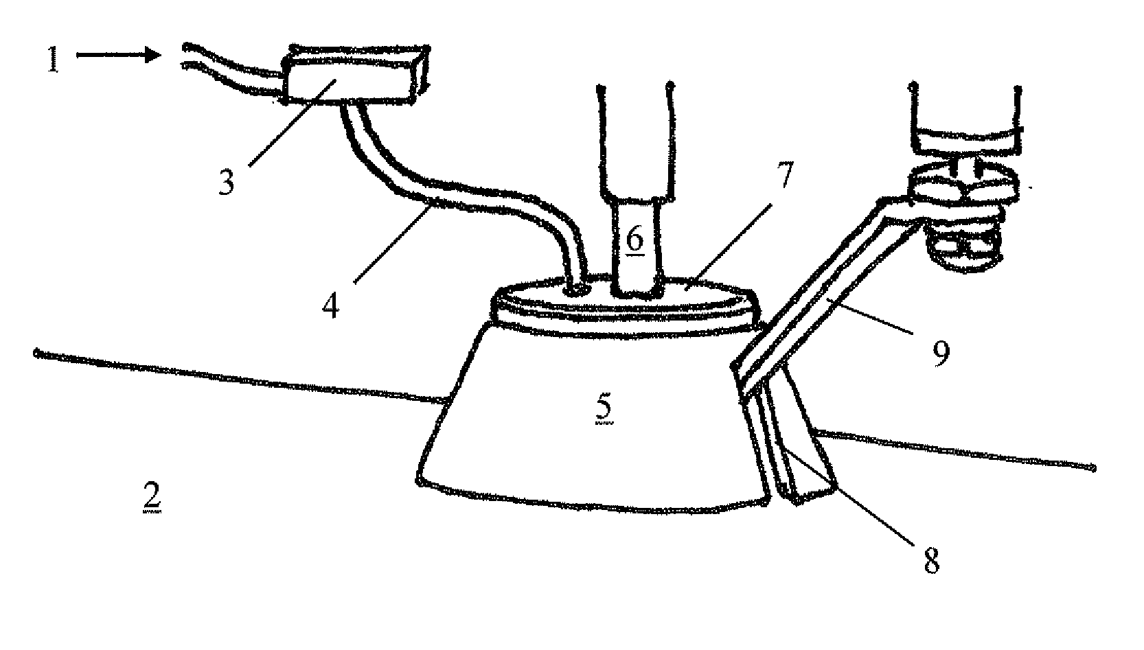
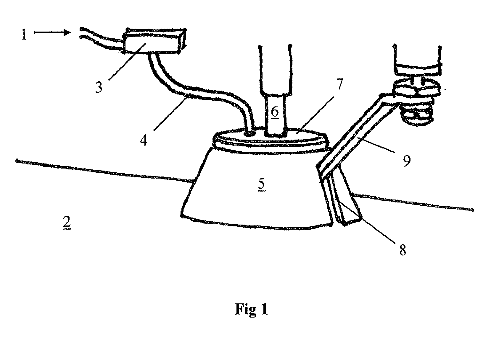
[0017]A preferred embodiment of the invention is shown in FIG. 1, where the collision sensing devise is adapted for use in water jet cutting. In this apparatus for water jet cutting a splatter shield 5 is utilized as deformable member, which encloses a nozzle 6 for water jet cutting. The splatter shield 5 comprises a side wall and an upper part. The side wall of the splatter shield 5 is formed as a frustum of a cone, se also FIGS. 2 and 3. The cone has a wider end and a narrower end. The wider end, which is turned downwards in the figures, is open and is during machining located just above the surface of the workpiece 2. The edge 11 of the wider end is located closer to the surface of the workpiece 2 than is the end of t...


PUM

PropertyMeasurementUnit
Shore hardnessaaaaaaaaaa

Abstract

The invention relates to a collision sensing device which can detect a collision between two or more objects. The collision sensing device comprises a deformable member (5) that defines a space (15) which can be assigned a pressure. In a first condition, the deformable member is undeformed, whereby the space (15) is assigned a first pressure (P1). In a second condition, the deformable member (5) is deformed whereby the space (15) is assigned a second pressure (P2). The pressure in the space is monitored. A collision with an object is detected when the pressure in the space changes from the first pressure to the second pressure.The invention can e.g. be applied in connection with machining, such as water jet cutting, but several other fields of application are also conceivable.

Description

FIELD OF INVENTION[0001]The invention relates to a collision sensing device, which is adapted to detect a collision between two or more objects. The invention also relates to an apparatus for machining that comprises said collision sensing device.[0002]In many situations, it is desirable to detect a collision between objects. One purpose can be avoiding collisions. Primary, the invention in directed towards detecting a collision between a tool and an obstacle in a workpiece during machining. Machining is here intended to in particular comprise all sorts of cutting machining such as water jet cutting, gas cutting, plasma cutting, laser cutting et cetera. During the machining it can on the one hand be desired to protect the tool, e.g. a nozzle of some kind, from damage due to a collision with an obstacle such as an unevenness in the workpiece. On the other hand, it can be desired to protect parts of the workpiece from damage due to collisions with a tool. The invention can also used i...

Claims


Application Information

Patent Timeline
Patent Type & Authority Applications(United States)
IPC IPC(8): B26D7/22G01L1/04
CPCB26D7/22Y10S83/01B26F3/004Y10T83/2066Y10T83/364Y10T83/088Y10T83/852B26F3/00B23Q5/58B23Q17/00
Inventor RYDH, JAN
Owner WATER JET SWEDEN
Why Eureka
Try Eureka