Electric rotating machine with salient poles

a technology of electric rotating machines and salient poles, which is applied in the direction of dynamo-electric machines, electrical apparatus, magnetic circuits, etc., can solve the problems of degrading the switching condition, increasing the loss of iron, and reducing the performance, so as to reduce the quantity of copper used or permanent magnets, the effect of improving the counteracting effect of armature reaction

Inactive Publication Date: 2010-07-15
VALEO EQUIP ELECTRIC MOTEUR
View PDF18 Cites 19 Cited by
  • Summary
  • Abstract
  • Description
  • Claims
  • Application Information

AI Technical Summary

Benefits of technology

[0014]According to a particular embodiment, two geometrically opposed salient poles are consecutive poles. The consecutive poles enable active material to be saved as the quantity of copper used or permanent magnets is reduced. The savings in copper can reach 50% at least for the inductor.
[0015]According to a particular feature, the consecutive poles comprise at least two slots...

Problems solved by technology

The drawbacks due to the magnetic armature reaction are therefore reduced, notably distortion of the magnetic waveforms in the air-gap, shift of the neutral line, degradation of the switching...

Method used


Image

  • Electric rotating machine with salient poles
  • Electric rotating machine with salient poles
  • Electric rotating machine with salient poles

Examples


first embodiment

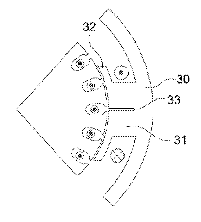
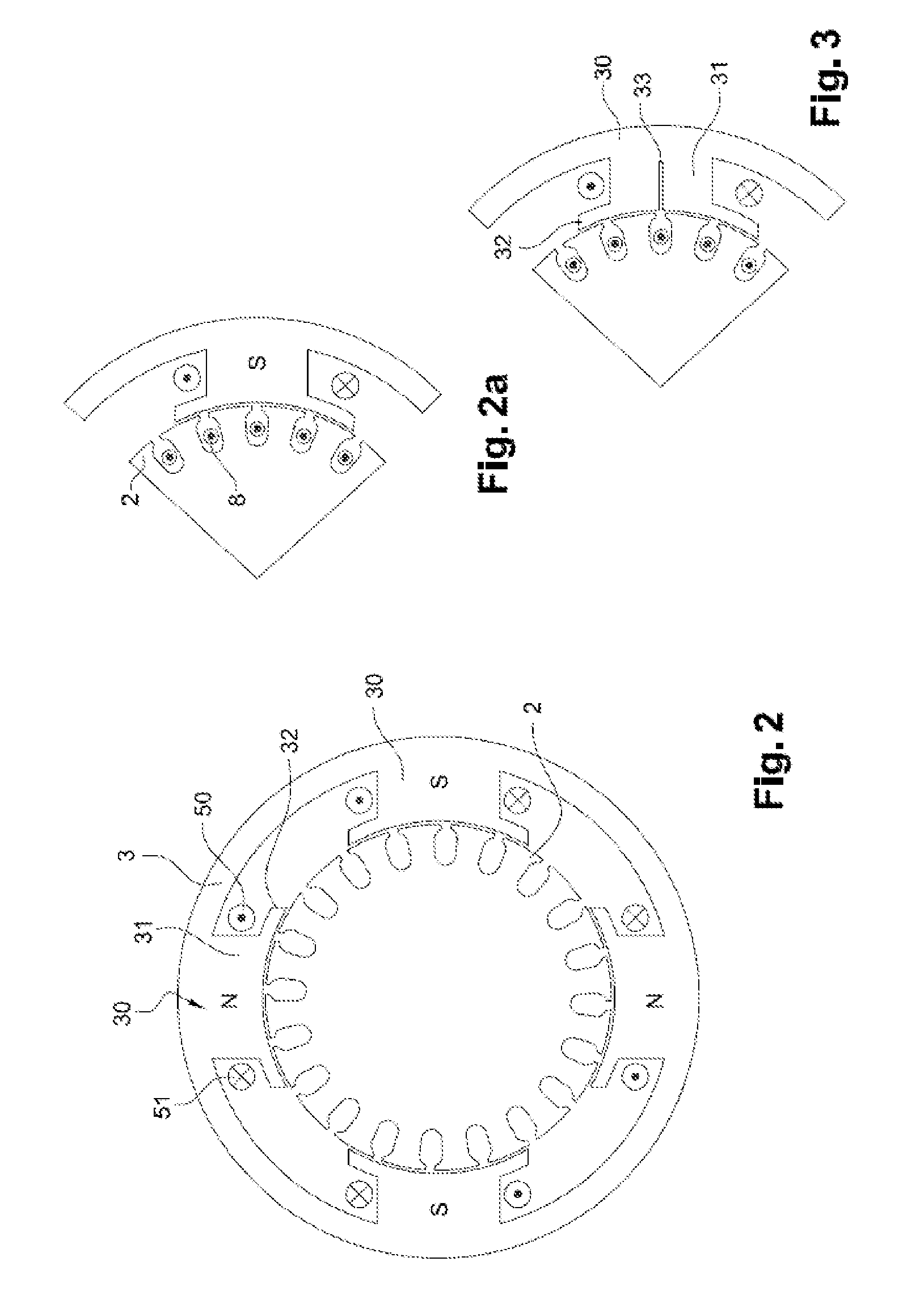
[0053]FIG. 3 illustrates a first embodiment, wherein salient pole 30 comprises a slot 33 located in the middle of polar core 30, but this slot 33 can also be offset from the centre of salient pole 30, for example by quarter of the width of the polar core.

second embodiment

[0054]FIG. 4 shows a second embodiment, wherein slot 33 is filled by a magnet 330. Magnet 330 is disposed so that its magnetization 331 is transverse to the inductive flux, therefore parallel to the armature flux, but in the opposite direction so as to produce a compensatory effect. Thus, the difference in permeability, the anisotropy and polarization counteract the armature reaction effects, and in particular the saturation which they cause.

third embodiment

[0055]FIG. 5a shows a third embodiment comprising a stator 3 with two not-wound poles constituting consecutive poles 40 enclosed by two wound salient poles 30, it being possible to have only one consecutive pole 40 on rotor 3. If there are several consecutive poles 30 these preferably all have the same electrical polarity; on FIG. 5a all the consecutive poles are north poles. Consecutive poles 40 are equipped with slots 41. These slots 41 can be relatively deep relative to consecutive pole 40 and can almost reach down to the edge of polar core 31. These slots 41 render consecutive pole 40 anisotropic and therefore counteract the armature reaction effects, the saturation of which they can cause in addition.

[0056]FIG. 5b illustrates an alternative to the previous embodiment, wherein slots 41 of consecutive poles 40 are closed by slot wedges 42.

[0057]FIG. 6 illustrates a salient pole 30 with a polar core 31 comprising several slots 33.

[0058]Salient pole 30 on FIG. 7 comprises several s...


PUM


Abstract

A DC electric rotating machine, such as a starter of an automotive vehicle, includes a stator with salient poles having at least four poles distributed uniformly over the circumference of the stator, a rotor disposed inside the stator, a set of brushes adapted for the electric supply of the rotor, and at least two geometrically opposed salient poles. Each pole includes at least one substantially radial slot in a plane parallel to the axis of rotation of the rotor and preferably passes through the axis of the rotor. By minimizing the reaction fields of the armature, utilization of the magnetic material of the parts of the stator is balanced and a harmful armature reaction effect, which increases saturation of the polar parts of the inductor and which leads to reduction in the driving magnetic torque, is mitigated.

Description

[0001]This application is a US Utility Patent Application, and claims priority to French Patent Application Number 09 / 50197 filed Jan. 15, 2009.FIELD OF INVENTION [0002]The present invention relates to an electric rotating machine, reversible or otherwise, more particularly a starter of an automotive vehicle.BACKGROUND OF THE INVENTION[0003]Electric rotating machines comprise an armature rotor and an inductive stator mounted in coaxial fashion, the stator surrounding the rotor. The rotor is integral with a drive shaft rotating inside a yoke. The stator has a plurality of magnetic poles disposed on an internal circumferential surface of a yoke and made up of salient poles around which are wound inductive wires, the unit constituting a wire wound inductor. The rotor, placed at the centre of the stator, comprises armature wires wound in notches.[0004]The inductive poles of the stator generally have “shoes”, that is to say lateral extensions at their apex as on a capital letter T.[0005]...

Claims


Application Information

Patent Timeline
IPC IPC(8): H02K23/42H02K1/14
CPCH02K23/42F02N11/00H02K1/17H02K21/38
Inventor LABBE, NICOLASDUPEUX, BENOITYONNET, JEAN-PAUL
Owner VALEO EQUIP ELECTRIC MOTEUR
Why Eureka
Try Eureka