
System and method for detection of eas marker shielding

Active Publication Date: 2010-07-15
SENCORMATIC ELETRONICS LLC
View PDF6 Cites 28 Cited by
  • Summary
  • Abstract
  • Description
  • Claims
  • Application Information

AI Technical Summary

Benefits of technology

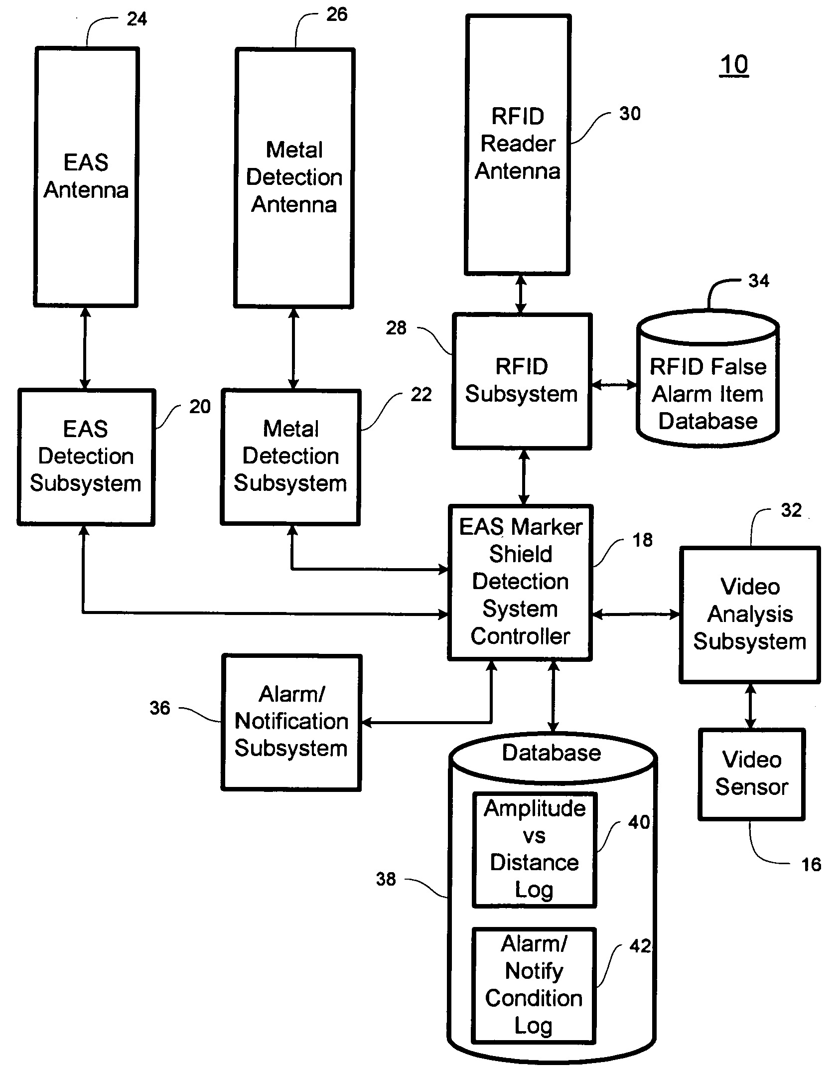
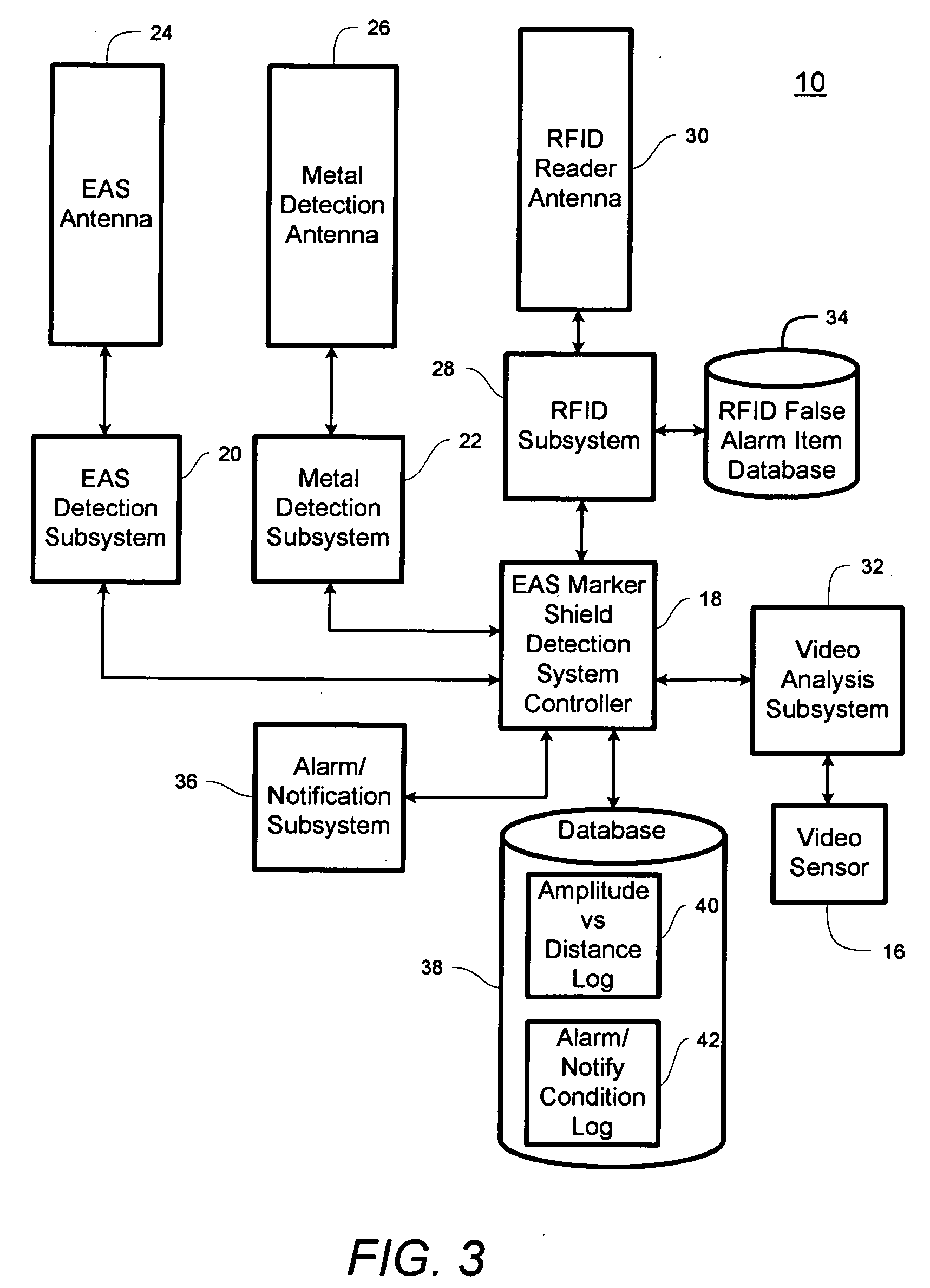
[0010]The present invention advantageously provides a method and system for detecting electronic article surveillance marker shielding by coordinating inputs from a variety of subsystems including an electronic article surveillance subsystem, a metal detection subsystem, a video analysis subsystem and a radio-frequency identification subsystem. Correlating known conditions to predefined object classes advantageously allows more accurate shielding detection and prevents false alarms.

Problems solved by technology

A major problem with this approach is that there are many metal objects and products that pass through the EAS system detection zone that are not related to theft.
Unfortunately, relying on amplitude is not entirely reliable because a foil lined bag that is physically close to a metal detector antenna may exhibit a responsive signal strength similar to that of a shopping cart that is located further away from the metal detector.
This problem forces the metal detection systems to be confined to narrow openings and to narrowly limit the range for positive detection of foil lined bags which causes the sensitivity of the system to be degraded.
In other words, the metal detectors and / or EAS systems are arranged such that shopping carts will not fit through the exits.
However, controlling the flow of traffic to eliminate false alarms from shopping carts interferes with the normal behavior of customers and degrades the customer experience.
Since a positive customer experience is extremely important to retailers, this approach is usually undesirable.
Eliminating products that cause false alarms also degrades the shopping experience and limits the customer choices that are extremely important to retailers.
Thus, this approach is also undesirable to retailers.

Method used


Image

  • System and method for detection of eas marker shielding
  • System and method for detection of eas marker shielding
  • System and method for detection of eas marker shielding

Examples


Embodiment Construction

[0024]Before describing in detail exemplary embodiments that are in accordance with the present invention, it is noted that the embodiments reside primarily in combinations of apparatus components and processing steps related to implementing a system and method for identifying items that are likely to be used as foil lined containers and identifying items entering a detection zone that could trigger false alarms in order to distinguish between real and false alarm conditions. Accordingly, the system and method components have been represented where appropriate by conventional symbols in the drawings, showing only those specific details that are pertinent to understanding the embodiments of the present invention so as not to obscure the disclosure with details that will be readily apparent to those of ordinary skill in the art having the benefit of the description herein.

[0025]As used herein, relational terms, such as “first” and “second,”“top” and “bottom,” and the like, may be used...


PUM


Abstract

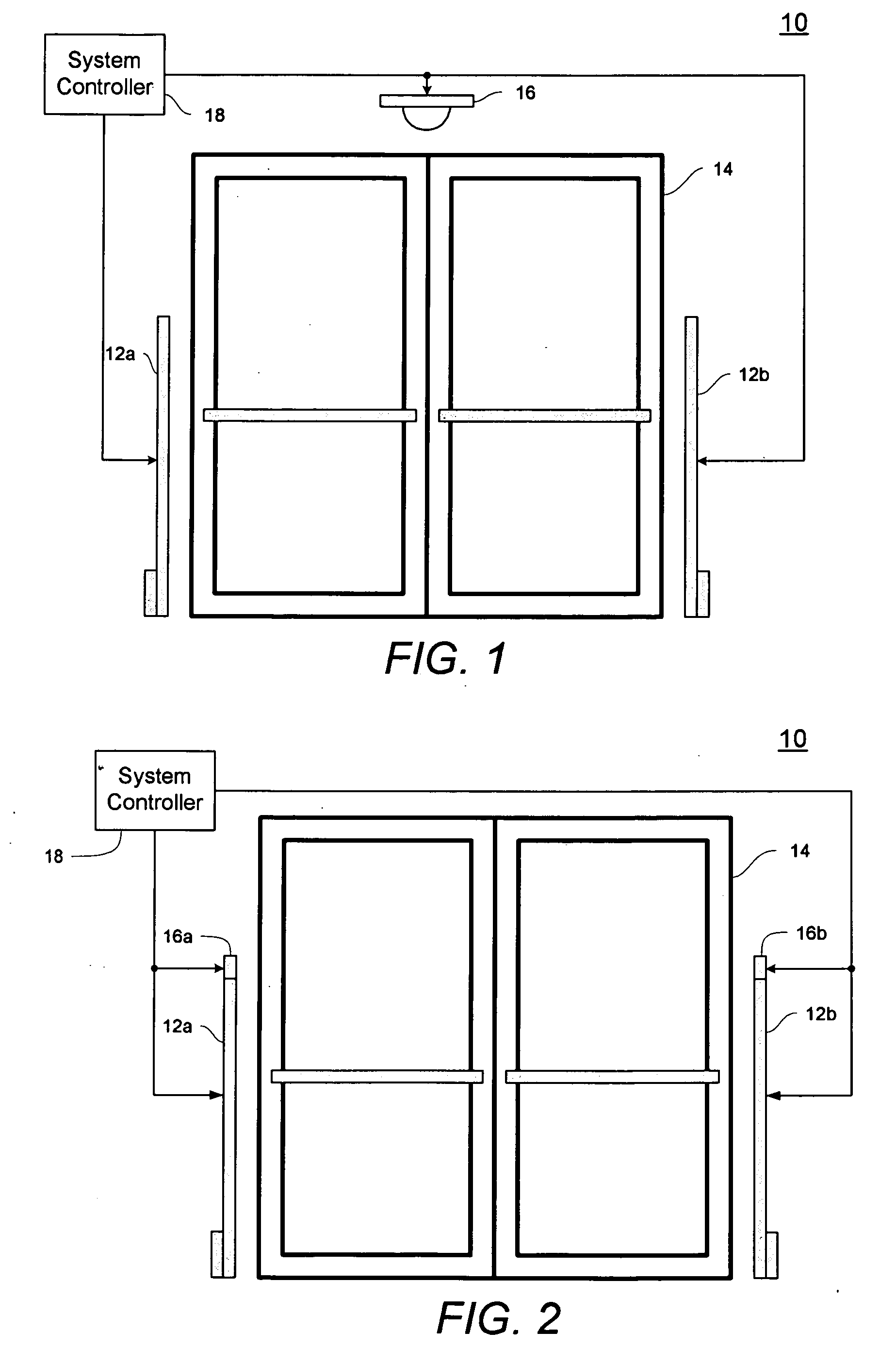
A system for detecting electronic article surveillance marker shielding includes electronic article surveillance (“EAS”), metal detection and video analysis subsystems communicatively coupled to a system controller. The EAS subsystem detects EAS markers within a detection zone. The metal detection subsystem detects metallic objects within the detection zone. The video analysis subsystem captures a video image of the metallic object. The system controller determines a probable classification for the metallic object and calculates a confidence weight for the probable classification. If the metallic object is identified as EAS marker shielding according to the probable classification and the corresponding confidence weight, an alert is generated.

Description

CROSS-REFERENCE TO RELATED APPLICATION[0001]n / aSTATEMENT REGARDING FEDERALLY SPONSORED RESEARCH OR DEVELOPMENT[0002]n / aFIELD OF THE INVENTION[0003]The present invention relates generally to a method and system to detect electronic article surveillance (“EAS”) marker shielding and more specifically to a method and system for detecting EAS marker shielding using a combination of metal detection, radio-frequency identification (“RFID”) and video sensors to identify detected metal items and prevent false alarms.BACKGROUND OF THE INVENTION[0004]A growing method to defeat electronic article surveillance (“EAS”) systems is the use of readily available metal foils such as aluminum foil to shield EAS markers from detection by an EAS system. Thieves often line the insides of shopping bags, handbags and backpacks with metal foil to provide a concealed compartment for placing items to be stolen while inside the store so that they can exit through the detection zone of an EAS exit systems withou...

Claims


Application Information

Patent Timeline
IPC IPC(8): G08B13/14H04N7/18
CPCG08B29/046G08B13/248G08B13/196
Inventor HALL, STEWART E.
Owner SENCORMATIC ELETRONICS LLC
Learn More