Highly heat integrated reformer for hydrogen production

a hydrogen production and reformer technology, applied in the field of hydrogen production reactors, can solve the problems of large deficit that must be covered by an external heat supply, increase resource consumption and cost, and high cost, and achieve the effects of facilitating the introduction and distribution of fuel, facilitating the collection and exit of combustion products, and facilitating the withdrawal of reforming products

Inactive Publication Date: 2010-07-15
HELBIO HYDROGEN & ENERGY PRODN SYST
View PDF4 Cites 87 Cited by
  • Summary
  • Abstract
  • Description
  • Claims
  • Application Information

AI Technical Summary

Benefits of technology

[0015]In another aspect of the invention the integrated combustor/steam reformer assembly includes a multitude of tubular sections defined by cylindrical walls separated from each other and supported on each end on plates machined as to allow the cylindrical walls to pass through them and to be in fluid connection with only one side of the plate. The sub-assembly of the tubular sections and the plates is enclosed with a cylindrical housing which isolates the space defined by the inner part of the housing and the plates from being in fluid connection with the surroundings. The inside wall of the tubular sections is coated with a catalyst that induces the desired reaction

Problems solved by technology

The problem lies in the low energy density of hydrogen which makes its transportation very inefficient and expensive.
Transporting hydrogen in compressed or liquid form requires specialized and bulky equipment that minimizes the amount than can be safely carried, increasing resource consumption and cost.
This becomes an even bigger issue in the first stages of the implementation when the low demand will not be able to justify costly infrastructure options such as pipeline networks.
Even so, there is a large deficit that must be covered by an external heat supply.
This is a rather inefficient arrangement

Method used


Image

  • Highly heat integrated reformer for hydrogen production
  • Highly heat integrated reformer for hydrogen production
  • Highly heat integrated reformer for hydrogen production

Examples


Embodiment Construction

[0026]The present invention is described in detail with reference to a few preferred embodiments illustrated in the accompanying drawings. The description presents numerous specific details included to provide a thorough understanding of the present invention. It will be apparent, however, to one skilled in the art that the present invention can be practiced without some or all of these specific details. On the other hand, well known process steps, procedures and structures are not described in detail as to not unnecessarily obscure the present invention.

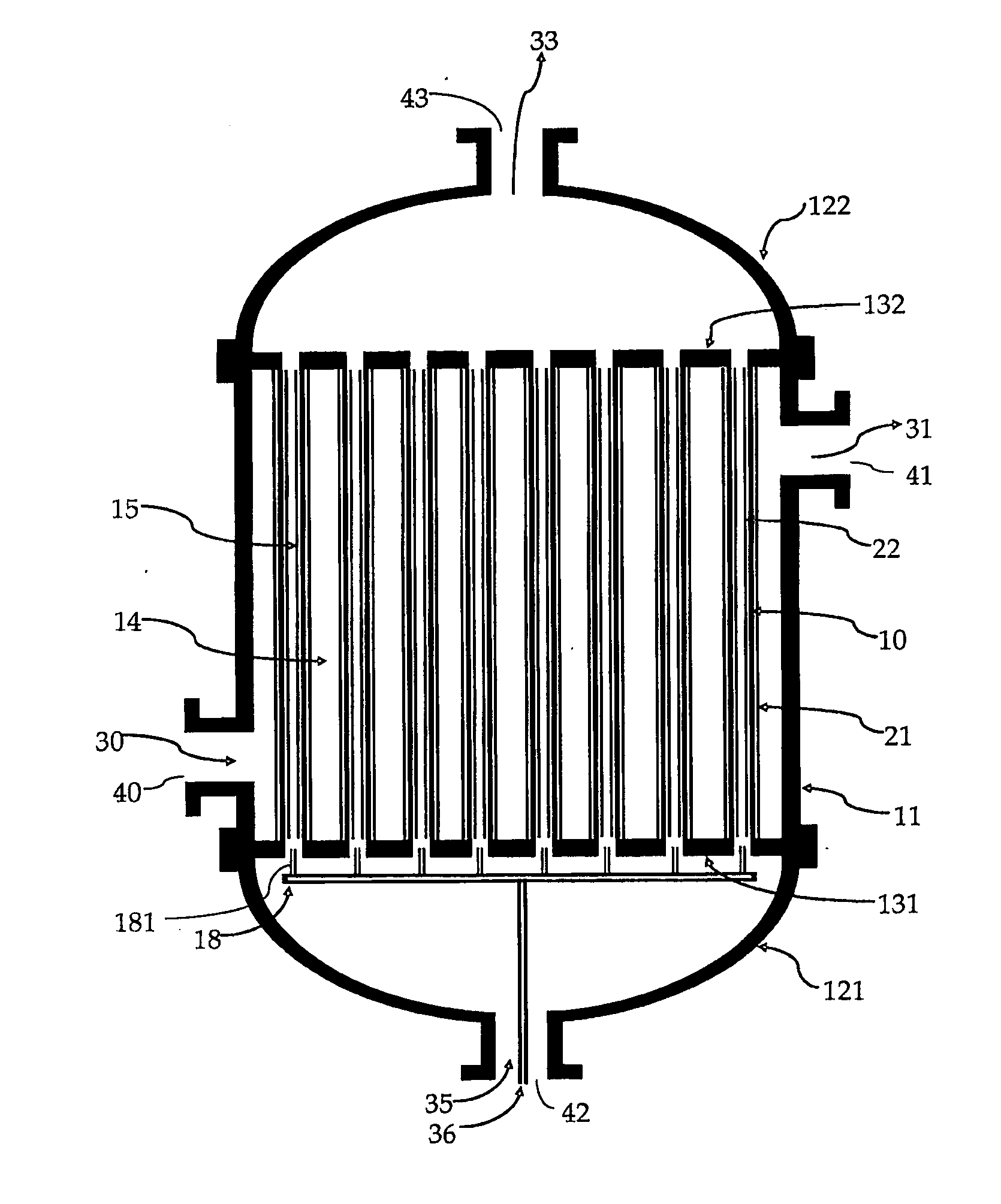
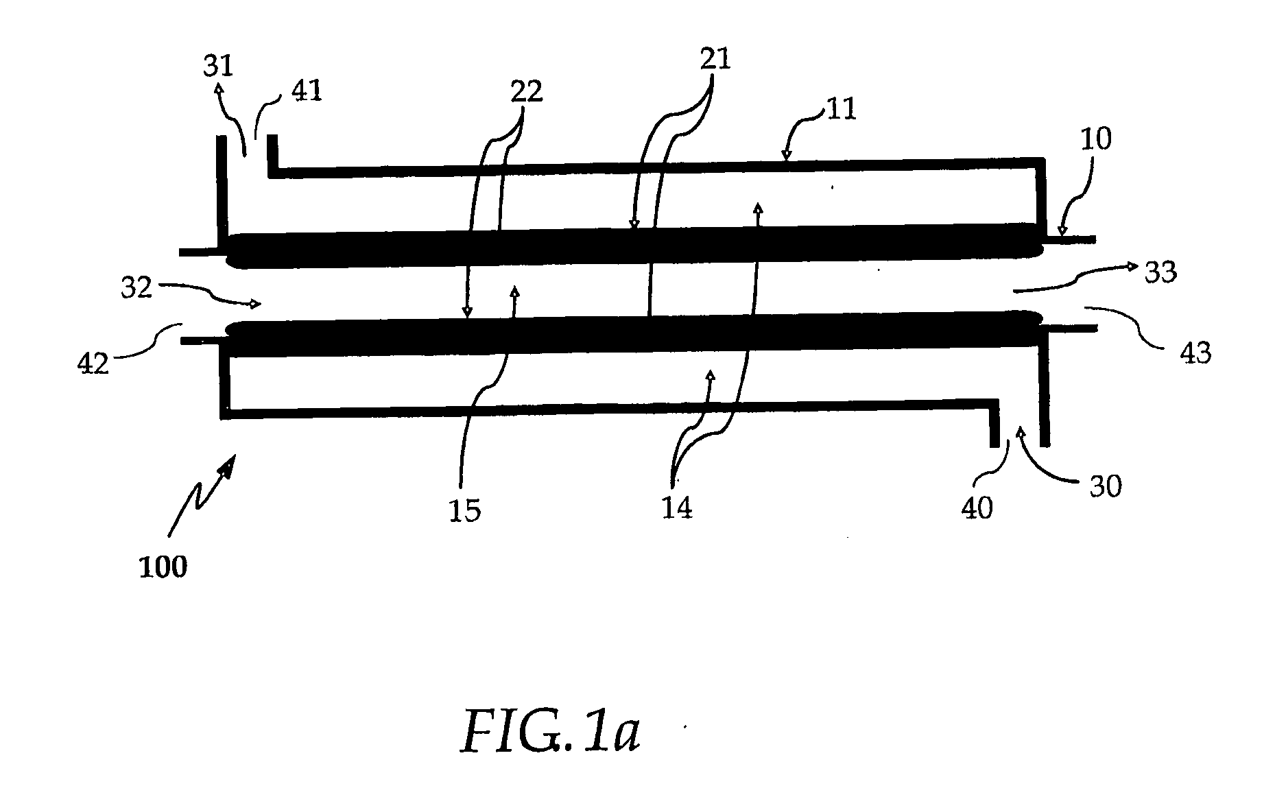
[0027]FIG. 1A illustrates the heat integrated reformer according to one embodiment of the present invention. The integrated combustor / steam reformer assembly includes a tubular section defined by a cylindrical wall 10 that separates the combustion zone 15 from the reforming zone 14. The assembly housing 11 acts as the reactor wall and defines an axially extending concentric annular passage in heat transfer relation with the tubular ...


PUM


Abstract

Described herein is a highly heat integrated steam reformer/combustor assembly that can be used in a fuel processor for hydrogen production from a fuel source. The assembly comprises a reforming section and a combustion section separated by a wall. Catalyst able to induce the reforming reactions is coated on the wall facing the reforming section. Catalyst able to induce the combustion reactions is coated on the wall facing the combustion section. A steam and fuel mixture is supplied to the reforming section where it is reformed to product hydrogen. A fuel and air mixture is supplied to the combustion section where it is combusted to supply the heat for the reformer. Catalytic combustion takes place on the combustion catalyst coated on one side of the wall while catalytic reforming takes place on the reforming catalyst coated on the other side of the wall. Heat transfer is very facile and efficient across the wall. Multiple such assemblies can be bundled to form reactors of any size.

Description

FIELD OF THE INVENTION[0001]This invention relates to reactors for hydrogen production and more particular to reactors where hydrocarbons are reformed to produce a hydrogen rich stream.BACKGROUND OF THE INVENTION[0002]The use of hydrogen as the new energy vector has gained wide acceptance and is progressing along the road to implementation. Hydrogen can be used in both internal combustion engines and fuel cells. Particularly, its usage in fuel cells to produce electricity or to co-generate heat and electricity represents the most environment friendly energy production process due to the absence of any pollutant emissions and is driven by the growing concerns over greenhouse gas emissions and air pollution. Most importantly, hydrogen can be produced from renewable energy sources such as biofuels, alleviating concerns over the long-term availability of fossil fuels and energy supply security. Applications of such systems include both mobile systems such as vehicle propulsion or auxili...

Claims


Application Information

Patent Timeline
IPC IPC(8): B01J8/02
CPCB01J19/006C01B2203/0811B01J2219/00117C01B2203/0233B01J19/2415C01B3/384B01J4/002B01J4/005B01J12/007B01J2219/00081B01J2219/00777C01B2203/1035C01B2203/0822B01J19/2425Y02P20/129Y02P20/10B01J8/02C01B3/38
Inventor VERYKIOS, XENOPHONLYGOURAS, DIMITRIOS K.
Owner HELBIO HYDROGEN & ENERGY PRODN SYST
Why Eureka
Try Eureka