Electrically-variable transmission

a transmission and variable technology, applied in the direction of electric propulsion mounting, transportation and packaging, gearing, etc., can solve the problem of much more important cost of tooling, and achieve the effect of reducing spin loss and cost, and simplifying assembly

Inactive Publication Date: 2010-07-15
GM GLOBAL TECH OPERATIONS LLC
View PDF6 Cites 67 Cited by
  • Summary
  • Abstract
  • Description
  • Claims
  • Application Information

AI Technical Summary

Benefits of technology

[0005]Various embodiments of electrically-variable transmissions are provided that have a first and a second motor / generator, a first and a second planetary gear set, and two torque-transmitting mechanisms, including a rotating-type clutch and a stationary-type clutch. The first torque-transmitting mechanism is selectively engagable to ground the ring gear of the second planetary gear set to the stationary member. The second torque-transmitting mechanism is selectively engagable to connect the sun gear of the first planetary gear set for common rotation with the ring gear of the second planetary gear set. An input member is connected for common rotation with a ring gear of the first planetary gear set. Carrier members of both of the planetary gear sets are connected for common rotation with one another, and with an output member, via one or more radial-extending hub members and axial-extending members or shafts. The rotor of the first motor / generator is connected for common rotation with the sun gear of the first planetary gear set. The rotor of the second motor / generator is connected for common rotation with the sun gear of the second planetary gear set. In each embodiment, the various components of the transmission are positioned relative to one another to minimize the number and / or size of interconnecting, axially-extending shafts and shells (i.e., axial-extending members spaced from the axis of rotation by radial-extending hub members and passing over (enveloping) other rotatable components). For example, the input member is radially surrounded by at least one of the planetary gear sets, and / or the first torque-transmitting mechanism is radially outward of and aligned with the second planetary gear set, and / or the output member extends radially from one of the planetary gear sets. Thus, spin losses and costs are reduced. Assembly may also be simplified.

Problems solved by technology

It is challenging to package the two motor / generators, planetary gear sets, and multiple torque-transmitting mechanisms necessary to achieve the desired modes of operation, while meeting other applicable dimensional limitations and achieving relatively simple assembly requirements.
Furthermore, although electrically variable transmissions are being mass-produced today, they are installed in only a very small fraction of the total number of vehicles produced today, and so engineering and tooling costs are much more important as compared with those costs for other types of transmissions.

Method used


Image

  • Electrically-variable transmission
  • Electrically-variable transmission
  • Electrically-variable transmission

Examples


second embodiment

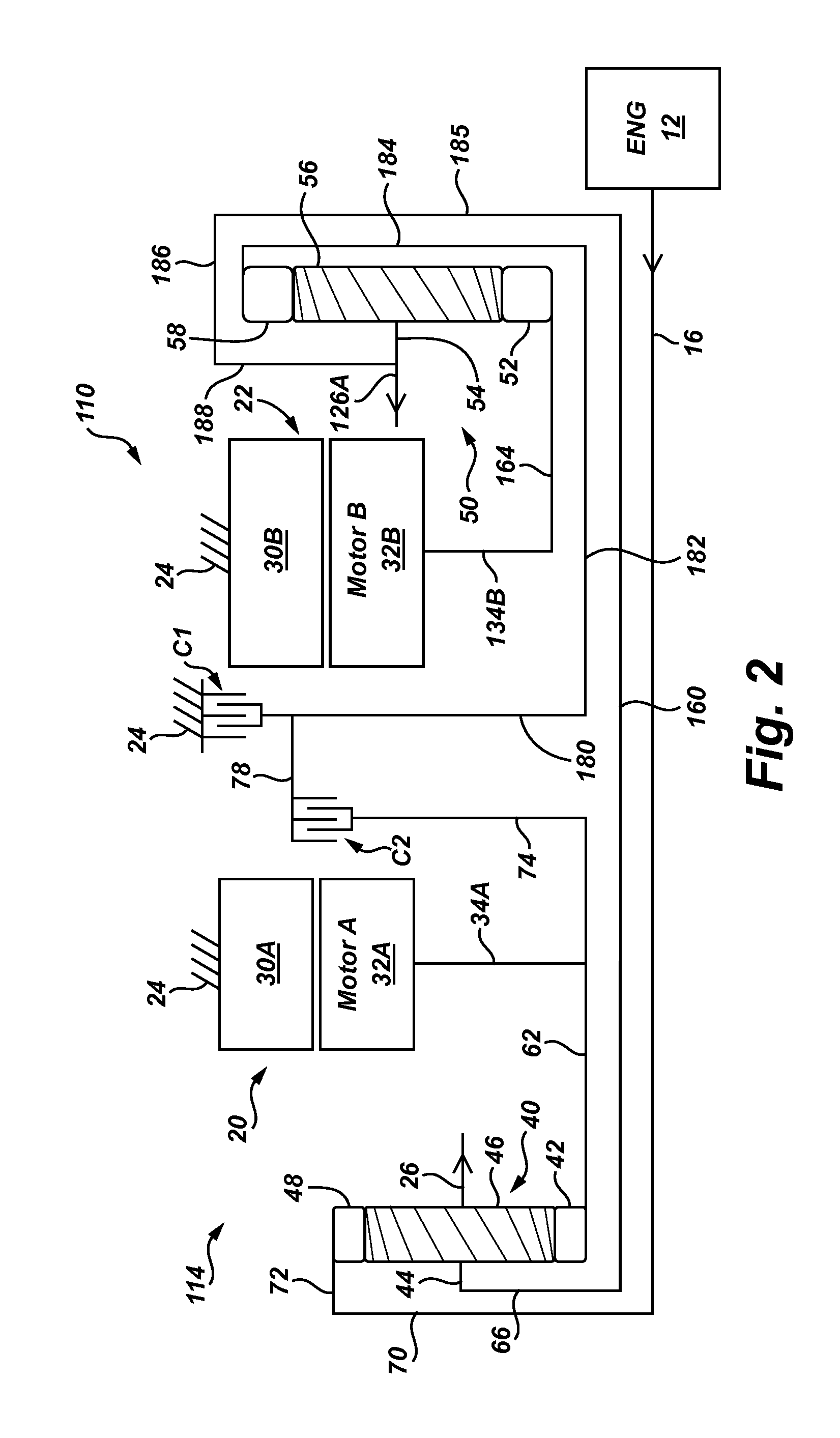
[0026]Referring to FIG. 2, powertrain 110 includes an engine 12 and an electrically variable transmission 114 having many of the same components, referred to with the same reference numbers, that function in the same way as shown and described with respect to the transmission 14 and powertrain 10 of FIG. 1. Although not shown in FIG. 2, a battery 36, inverter 38, and controller 39 are connected with the stators 30A, 30B as shown and described in FIG. 1.

[0027]Transmission 114 is configured so that planetary gear set 40 is positioned axially between a radially-extending end wall (not shown) of the casing 24 and the motor / generator 20. Clutches C1 and C2 are positioned axially between the motor / generators 20, 22. Planetary gear set 50 is positioned axially between the motor / generator 22 and a radially-extending opposing end wall (not shown) of the casing 24. Hub member 134B and axially-extending member 164 connect the rotor 32B for common rotation with the sun gear 52. Transmission 114...

third embodiment

[0028]Referring to FIG. 3, powertrain 210 includes an engine 12 and an electrically variable transmission 214 having many of the same components, referred to with the same reference numbers, that function in the same way as shown and described with respect to the transmission 14 and powertrain 10 of FIG. 1. Although not shown in FIG. 3, a battery 36, inverter 38, and controller 39 are connected with the stators 30A, 30B as shown and described in FIG. 1.

[0029]Transmission 214 is configured so that motor / generator 22 is positioned axially between a radially-extending end wall (not shown) of the casing 24 and the planetary gear set 50. Clutch C1 is positioned radially outward and aligned with the ring gear 58 of planetary gear set 50. Clutch C2 is positioned axially between motor / generator 20 and gear set 50 and may be aligned with ring gear 58. Motor / generator 20 is positioned axially between the clutch C2 and the planetary gear set 40. Planetary gear set 40 is positioned axially betw...

fourth embodiment

[0031]Referring to FIG. 4, powertrain 310 includes an engine 12 and an electrically variable transmission 314 having many of the same components, referred to with the same reference numbers, that function in the same way as shown and described with respect to the transmission 14 and powertrain 10 of FIG. 1. Although not shown in FIG. 4, a battery 36, inverter 38, and controller 39 are connected with the stators 30A, 30B as shown and described in FIG. 1.

[0032]Transmission 314 is configured so that motor / generator 22 is positioned axially between a radially-extending end wall (not shown) of the casing 24 and the planetary gear set 50. Clutch C1 is positioned radially outward and aligned with the ring gear 58 of planetary gear set 50. Clutch C2 is positioned axially between motor / generator 20 planetary gear set 50. Planetary gear set 40 is positioned axially between the clutch C2 and the motor / generator 20. Motor / generator 20 is positioned axially between the planetary gear set 40 and ...


PUM


Abstract

Various embodiments of electrically-variable transmissions have first and second motor-generators, first and second planetary gear sets, and two torque-transmitting mechanisms, including a rotating-type torque-transmitting mechanism and a stationary-type torque-transmitting mechanism. An input member is connected for common rotation with a ring gear of the first planetary gear set. Carrier members of both of the planetary gear sets are connected for common rotation with one another, and with an output member, via one or more radial-extending hub members and an axial-extending member or shaft. The first motor / generator is connected for common rotation with the sun gear of the first planetary gear set. The second motor / generator is connected for common rotation with the sun gear member of the second planetary gear set. In each embodiment, the various components of the transmission are positioned relative to one another to minimize the number and / or size of interconnecting shafts and shells.

Description

CROSS-REFERENCE TO RELATED APPLICATIONS[0001]This application claims the benefit of U.S. Provisional Application Ser. No. 61 / 144,567, filed Jan. 14, 2009, which is hereby incorporated by reference in its entirety.TECHNICAL FIELD[0002]The invention relates to an electrically-variable transmission having two motor-generators and two planetary gear sets.BACKGROUND OF THE INVENTION[0003]Electrically-variable transmissions typically have an input member, an output member, and two electric motor / generators connected to different members of planetary gear sets. Clutches allow one or more electrically-variable modes of operation, fixed speed ratio modes, and an electric-only (battery-powered) mode. Electrically-variable transmissions may improve vehicle fuel economy in a variety of ways, primarily by using one or both of the motor / generators for vehicle braking and using the regenerated energy to power the vehicle electrically, with the engine off. The engine may be turned off at idle, duri...

Claims


Application Information

Patent Timeline
Patent Type & Authority Applications(United States)
IPC IPC(8): F16H3/72
CPCB60K1/02B60K6/365B60K6/40B60K6/445B60K6/547Y02T10/6239F16H2037/102F16H2037/104F16H2200/2007F16H2200/2035F16H3/728Y02T10/62
Inventor WITTKOPP, SCOTT H.HOLMES, ALAN G.HART, JAMES M.GROCHOWSKI, EDWIN T.WOODEN, ELIZABETH I.
Owner GM GLOBAL TECH OPERATIONS LLC
Why Eureka
Try Eureka