
Processing apparatus, center-hole working system, center-hole position deciding program, and center-hole position deciding method

a technology of center-hole position and processing equipment, applied in analogue processes, manufacturing tools, instruments, etc., can solve the problems of reducing the need for final balance adjustment, requiring effort, time and cost, and greatly changing the statistical tendency, so as to reduce the necessity of final balance adjustment.

Active Publication Date: 2010-07-15
KOMATSU NTC LTD
View PDF2 Cites 14 Cited by
  • Summary
  • Abstract
  • Description
  • Claims
  • Application Information

AI Technical Summary

Benefits of technology

[0015]In response to this, an object of the present invention is to provide a technology for easily and properly deciding a center-hole position in a crankshaft.
[0032]According to the center-hole position deciding method, the center-hole position can be appropriately decided before the predetermined working processing is executed for the material crankshaft so that the rotational imbalance amount is within the predetermined allowable range after the predetermined working processing is executed. The configuration can effective prevent the material crankshaft from being produced as an inferior product. Additionally the configuration can reduce necessity of the final balance adjustment with respect to the crankshaft after working.

Problems solved by technology

Accordingly, there is a drawback of requiring effort, time and cost.
Additionally, when the product lot is changed, a drawback is produced that statistical tendency is greatly changed.
To do the dynamic balance test, there is a drawback that preparation of a quite expensive balance meter is required.

Method used


Image

  • Processing apparatus, center-hole working system, center-hole position deciding program, and center-hole position deciding method
  • Processing apparatus, center-hole working system, center-hole position deciding program, and center-hole position deciding method
  • Processing apparatus, center-hole working system, center-hole position deciding program, and center-hole position deciding method

Examples


Embodiment Construction

[0040]An embodiment of the present invention will be hereinafter explained with reference to the accompanying figures. Note the following embodiment does not limit inventions described in the section of Claims, and means for solving problems is not necessarily required to have all the combinations of characteristics to be explained in the embodiment.

Material Crankshaft

[0041]First, an example material crankshaft will be hereinafter explained prior to explanation of a crankshaft working system including a processing apparatus according to an embodiment of the present invention.

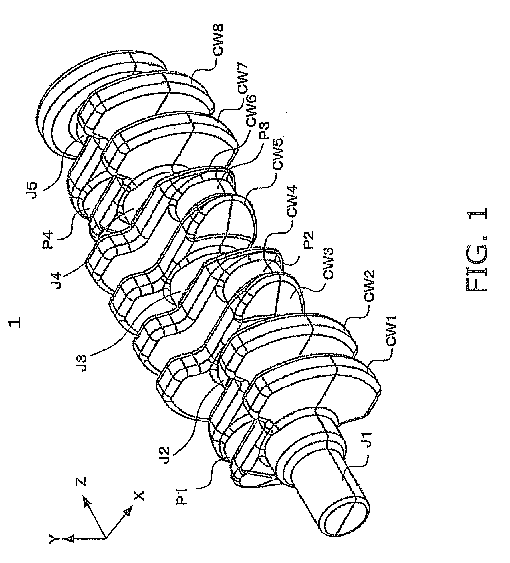
[0042]FIG. 1 is an external oblique view of a material crankshaft according to an embodiment of the present invention. The material crankshaft is used for the serial 4-cylinder engine.

[0043]The material crankshaft 1 is formed with an upper mold (top mold) and a lower mold (bottom mold), for instance. The material crankshaft 1 includes main journals J (J1 to J5), pin journals P (P1 to P4) and counterweights CW (C...


PUM


Abstract

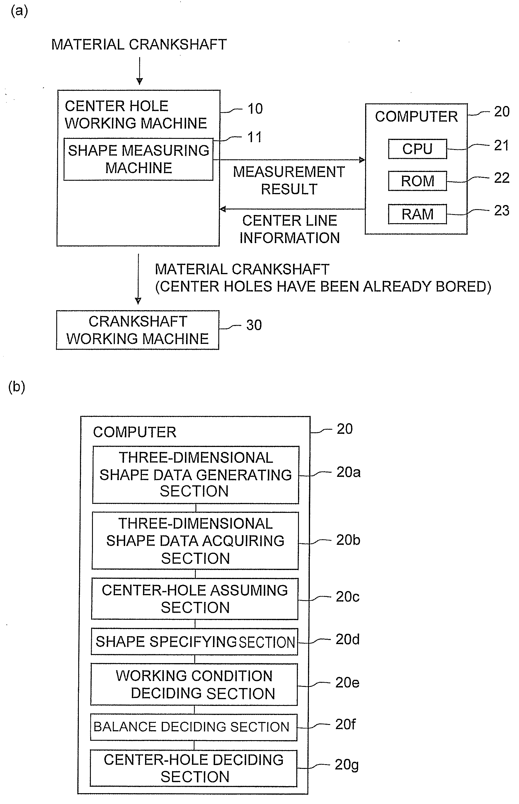
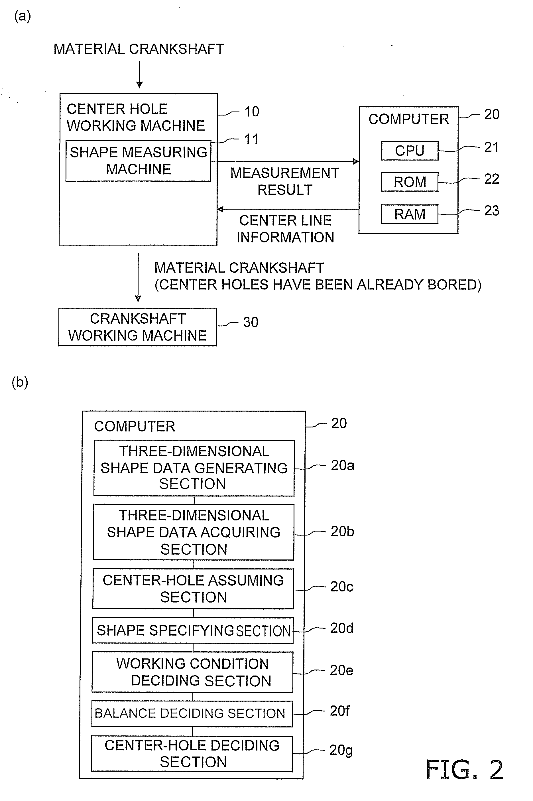
A processing apparatus includes a three-dimensional shape data acquiring section, a tentative center-hole position determining section, a shape simulating section, a balance deciding section, and a center-hole deciding section. The tentative center-hole position determining section is configured to determine a tentative position of the center holes based on the three-dimensional shape data. The shape simulating section is configured to obtain a simulated shape of the material crankshaft after a working is simulated for the material crankshaft based on the tentative position of the center holes as a reference. The balance deciding section is configured to decide whether a rotational imbalance amount in the simulated shape is within a predetermined allowable range. The center-hole deciding section is configured to decide the tentative position as an actual boring position of the center holes when the rotational imbalance amount is within the predetermined allowable range.

Description

CROSS-REFERENCE TO RELATED APPLICATIONS[0001]This national phase application claims priority to Japanese Patent Application No. 2007-201323, filed on Aug. 1, 2007. The entire disclosure of Japanese Patent Application No. 2007-201323 is hereby incorporated herein by reference.TECHNICAL FIELD[0002]The present invention relates to a processing apparatus for deciding a position of a center-hole, a center-hole working system, a center-hole position deciding program and a center-hole position deciding method, in boring a center-hole in a crankshaft to be used for engines of automobiles and the like.BACKGROUND ART[0003]A crankshaft is normally used while it is installed in an engine. When the rotational imbalance occurs in the crankshaft, a variety of problems occur (e.g., generation of vibration in the engine revolution). Therefore, the amount of the rotational imbalance (hereinafter simply referred to as “an imbalance value”) of a crankshaft is required to be in a predetermined allowable...

Claims


Application Information

Patent Timeline
Patent Type & Authority Applications(United States)
IPC IPC(8): G06F19/00B23Q17/00G01M1/24G01M1/30
CPCG01M1/24B23Q17/00G01B21/20G01M1/30
Inventor YOSHIMOTO, AKIHIRO
Owner KOMATSU NTC LTD
Learn More