Avoidance manoeuvre generator for an aircraft

a generator and aircraft technology, applied in the field of collision avoidance systems, can solve the problems of limited maneuverability, poor maneuvering performance, and the general poorness of maneuverability, and achieve the effect of reducing the number of aircra

Active Publication Date: 2010-07-15
SAAB AB
View PDF3 Cites 34 Cited by
  • Summary
  • Abstract
  • Description
  • Claims
  • Application Information

AI Technical Summary

Benefits of technology

[0017]Determining the normal load (nz), and the bank angle (Φ) based o

Problems solved by technology

In particular it relates to collision avoidance systems for aerial vehicles having limited maneuverability.
However, for contemporary UAVs, the maneuver performance is generally very poor.

Method used


Image

  • Avoidance manoeuvre generator for an aircraft
  • Avoidance manoeuvre generator for an aircraft
  • Avoidance manoeuvre generator for an aircraft

Examples


case 1

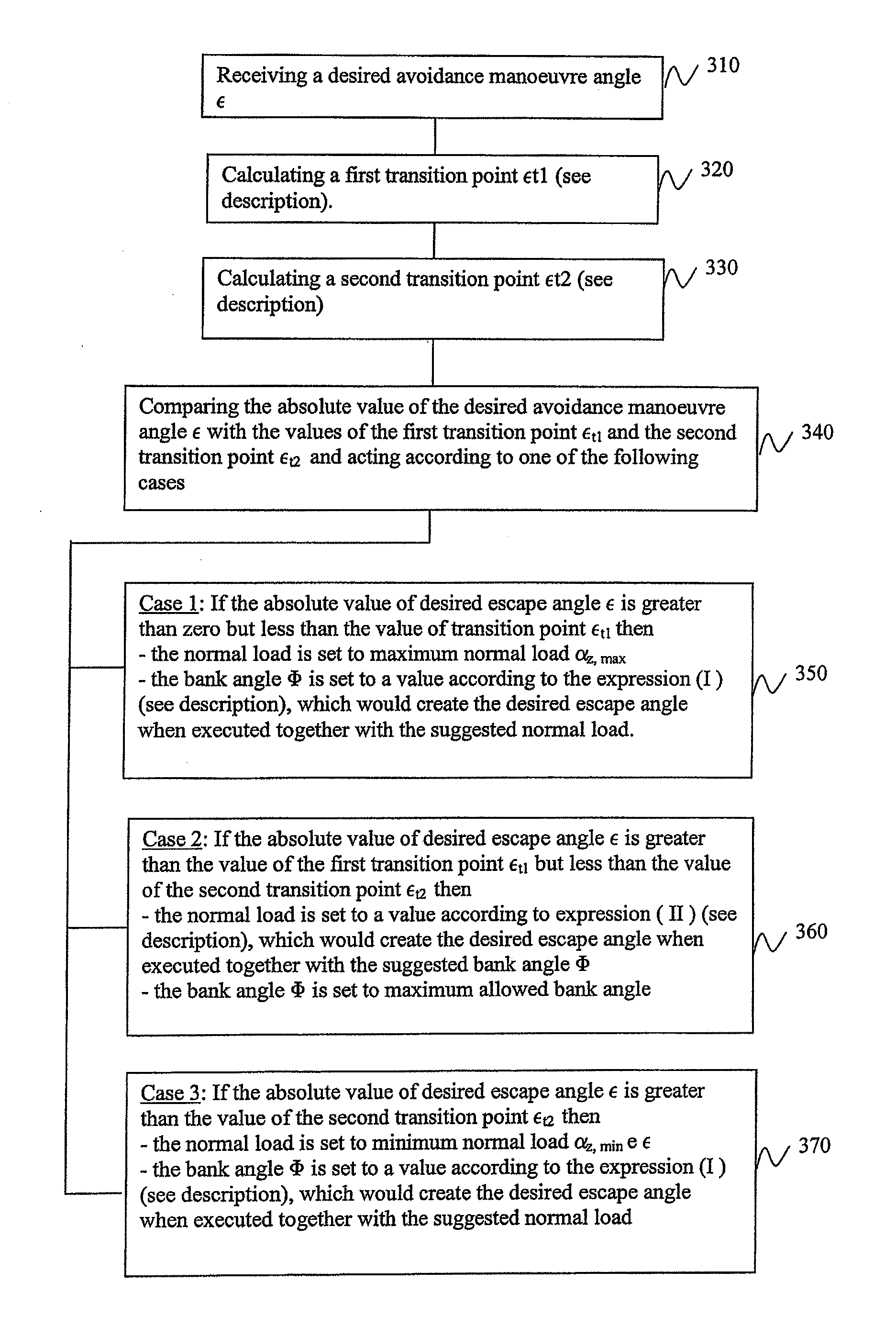
[0103] If 350 the absolute value of desired avoidance maneuver angle ε is greater than zero but less than the value of transition point εt1 then the suggested parameters for avoidance maneuver is set as follows:[0104]the normal load is set to maximum normal load nz,max [0105]the bank angle Φ is set to a value according to the expression (I) above, which would create the desired avoidance maneuver angle when executed together with the suggested normal load

case 2

[0106] If 360 the absolute value of desired avoidance maneuver angle ε is greater than the value of the first transition point εt1 but less than the value of the second transition point εt2 then the suggested parameters for avoidance maneuver is set as follows:[0107]the normal load is set to a value according to expression (II) above, which would create the desired avoidance maneuver angle when executed together with the suggested bank angle Φ;[0108]the bank angle Φ is set to maximum allowed bank angle;

case 3

[0109] If 370 the absolute value of desired avoidance maneuver angle ε is greater than the value of the second transition point εt2 then the suggested parameters for avoidance maneuver is set as follows[0110]the normal load is set to minimum normal load nz,min; [0111]the bank angle Φ is set to a value according to the expression (I) above, which would create the desired avoidance maneuver angle ε when executed together with the suggested normal load.

Less than Full Maneuvering

[0112]Sometimes it may prove advantageous not to use the full maneuvering capabilities of the aircraft in question. One known reason for this is that an optimizer or an optimizing function of a collision avoidance maneuver selector may need a smoother function to work with than that provided by the aforementioned method, otherwise it may happen that a suboptimal Avoidance Maneuver Angle eventually may be chosen. There may also be a need to optimize the maneuver envelope to provide a bias toward a desired type of...


PUM


Abstract

A method for automatically determining an avoidance maneuver in an automatic collision avoidance system of an aircraft. A maximum kinematic acceleration envelope is determined by determining a multitude of avoidance maneuver angle kinematic acceleration pairs in a kinematic acceleration plane, and interpolating gaps between points, thus creating a curve. The curve is called maximum kinematic acceleration envelope. The curve may also be approximated by an analytical expression. An adjusted kinematic acceleration envelope is formed in the plane by forming a new envelope. The new envelope at each point laying closer to or at the same distance from an origin as the points of the maximum kinematic acceleration envelope and such that there is only one value of the kinematic acceleration a for a given avoidance maneuver angle. An avoidance maneuver angle is received for which a suitable bank angle and a suitable normal load is to be determined. Determining The magnitude of the kinematic acceleration a corresponding to the adjusted kinematic acceleration envelope for the avoidance maneuver angle is determined by reading the envelope curve, or if the curve is an analytical expression, calculating the curve by using the analytical expression. The normal load is determined based on the kinematic acceleration, and the avoidance maneuver angle. The bank angle is determined based on the kinematic acceleration and the avoidance maneuver angle.

Description

TECHNICAL FIELD[0001]The present invention relates to collision avoidance systems for controlling the maneuvering of an aircraft to avoid a collision with an object likely to collide with the aircraft if it maintains current course, altitude and speed. In particular it relates to collision avoidance systems for aerial vehicles having limited maneuverability. Even in more particular it relates to such systems for Unmanned Aerial Vehicles (UAVs), and Autonomous Aerial Vehicles (AAVs) that can take decisions by themselves without consulting a pilot on the ground, being controlled by limited remote control or no remote control at all.BACKGROUND[0002]Low maneuverability aircraft like UAVs can be remotely controlled or fly autonomously based on pre-programmed flight plans or having more complex dynamic automation systems. UAVs are currently used in a number of military roles, including reconnaissance and attack. They are also used in a small but growing number of civil applications such a...

Claims


Application Information

Patent Timeline
IPC IPC(8): G08G5/04G01S13/933
CPCG05D1/101G08G5/045G08G5/0078G08G5/0069G05D1/106
Inventor PETRINI, ERIK
Owner SAAB AB
Why Eureka
Try Eureka