
Computer readable storage medium storing program for generating reticle data, and method of generating reticle data

Active Publication Date: 2010-07-15
CANON KK
View PDF31 Cites 3 Cited by
  • Summary
  • Abstract
  • Description
  • Claims
  • Application Information

AI Technical Summary

Benefits of technology

[0020]The present invention provides a technique advantageous for

Problems solved by technology

However, the formation of such fine patterns is greatly affected by diffraction of light.
The pattern may be rounded at the corner or shortened, or the shape accuracy may greatly decrease.
As a result, the contact hole pattern to be transferred and the auxiliary pattern strongly interfere with each other, whereby the target contact hole pattern can be exposed successfully.
As patterns are becoming finer and come close to the limit of resolution, it becomes difficult to resolve them.
This is because the contrast is low near the limit of resolution and no desired depth can be attained owing to poor focusing characteristic.
As a problem intrinsic to line patterns, the proximity effect is significant and the shape distorts, failing to reproduce an arbitrary shape.
However, the illumination conditions are not always optimal for each pattern which forms a reticle pattern.
If an auxiliary pattern is obtained based on such an aerial image, its shape may become complicated.
Even if a reticle pattern is determined by calculation, no reticle may be produced actually owing to an excessively complicated shape of a fine auxiliary pattern.

Method used


Image

  • Computer readable storage medium storing program for generating reticle data, and method of generating reticle data
  • Computer readable storage medium storing program for generating reticle data, and method of generating reticle data
  • Computer readable storage medium storing program for generating reticle data, and method of generating reticle data

Examples


first embodiment

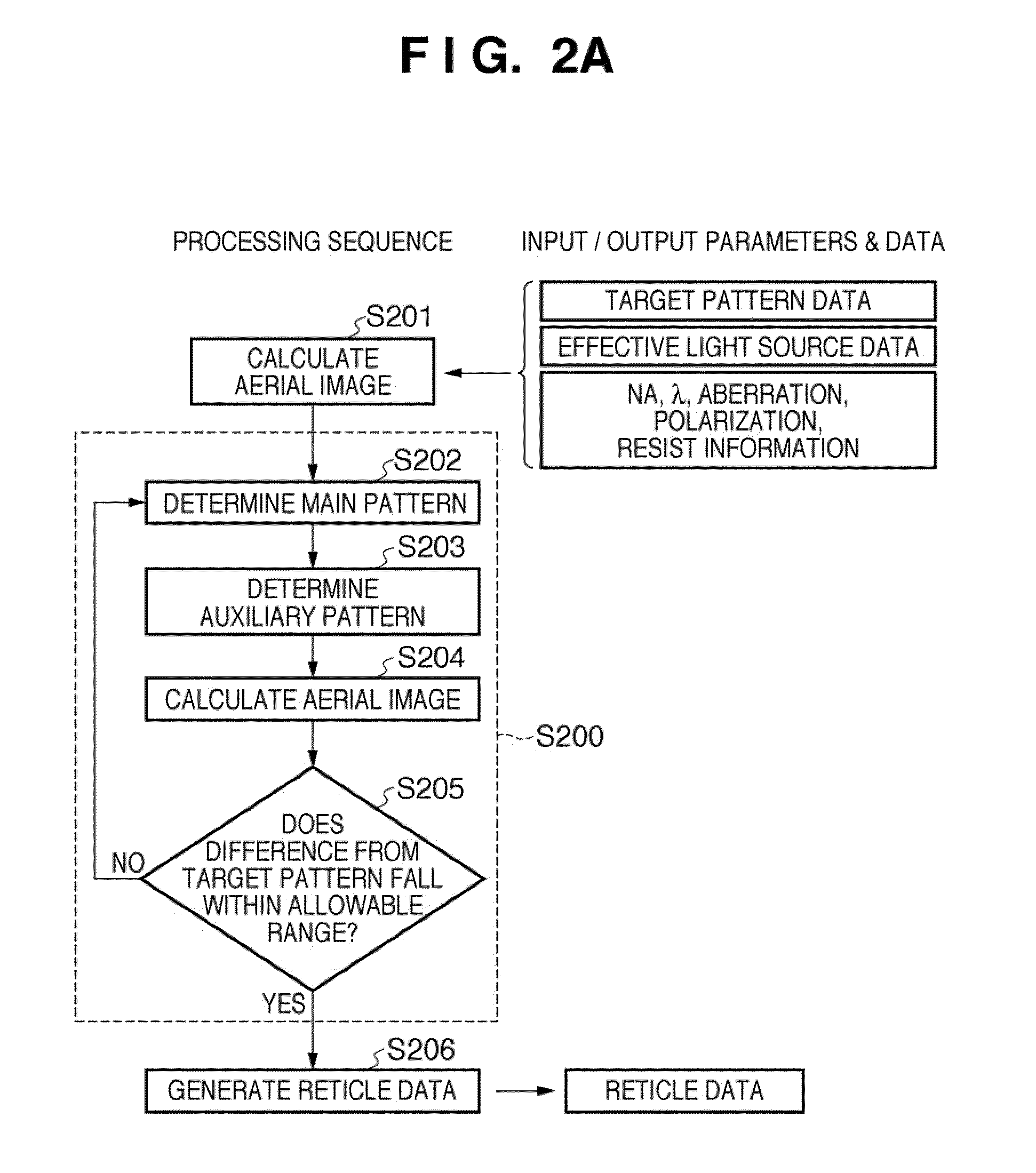
[0122]An embodiment of reticle data generating processing shown in FIG. 3A will be described. In this embodiment, target patterns are classified into a plurality of direction groups. For each direction group, a main pattern is determined by optical proximity correction under a partial light source corresponding to the direction. An auxiliary pattern which interferes with the main pattern is determined.

[0123]The exposure apparatus has an ArF light source which emits exposure light with a wavelength of 193 nm. The projection optical system has an NA of 1.35 and optical system is aberration free. No resist is considered.

[0124]Target patterns are line patterns as shown in FIG. 4, and have a line width of 45 nm and a length of 675 nm. In FIG. 4, a blank portion is a light-transmitting portion, the line pattern is a light-shielding pattern having a transmittance of 0, and the transmittance of the background is 1. All phases are 0, and the unit is nm.

[0125]An effective light source used fo...

second embodiment

[0136]An embodiment of reticle data generating processing shown in FIG. 3A will be described. In this embodiment, target patterns are classified into a plurality of direction groups. For each direction group, a main pattern is determined by optical proximity correction under a partial light source corresponding to the direction. An auxiliary pattern which interferes with the main pattern is determined.

[0137]The exposure apparatus is identical to that in the first embodiment. More specifically, the exposure apparatus has an ArF light source which emits exposure light with a wavelength of 193 nm. The projection optical system has an NA of 1.35 and a optical system is aberration free. No resist is considered.

[0138]Target patterns are five bar line patterns as shown in FIG. 13, and have a line width of 45 nm. The long bar at the center has a length of 1,350 nm, and the remaining bars have a length of 675 nm. In FIG. 13, a blank portion is a light-transmitting portion, the line pattern i...

third embodiment

[0144]An embodiment of reticle data generating processing shown in FIGS. 3B-1 and 3B-2 will be described. In this embodiment, main patterns are determined based on all target patterns using an effective light source as an illumination condition. Thereafter, an auxiliary pattern is determined using each partial light source as an illumination condition.

[0145]The exposure apparatus has an ArF light source which emits exposure light with a wavelength of 193 nm. The projection optical system has an NA of 1.35 and a optical system is aberration free. No resist is considered.

[0146]Target patterns line patterns which form an L shape as shown in FIG. 17, and have a line width of 45 nm and a length of 675 nm in both the longitudinal and lateral directions. In FIG. 17, a blank portion is a light-transmitting portion, the line pattern is a light-shielding pattern having a transmittance of 0, and the transmittance of the background is 1. All phases are 0, and the unit is nm.

[0147]An effective l...


PUM


Abstract

A computer readable storage medium stores a program for generating reticle data for producing a reticle used in an exposure apparatus, the program including the steps of classifying target patterns to be formed on a substrate into a plurality of direction groups, extracting, for each of the plurality of direction groups, a region suited to resolution of a target pattern belonging to the direction group from an effective light source distribution formed on a pupil of a projection optical system by an illumination optical system, thereby determining the extracted region as a partial light source, executing, for each of a plurality of partial light sources determined in the step of extracting a region, processing of determining a pattern to be placed on a reticle when each partial light source is used as an illumination condition, and merging patterns determined in the step of executing processing.

Description

BACKGROUND OF THE INVENTION[0001]1. Field of the Invention[0002]The present invention relates to a computer readable storage medium storing a program for generating reticle data for producing a reticle used in an exposure apparatus, and a method of generating reticle data.[0003]2. Description of the Related Art[0004]A semiconductor device is manufactured by repeating a photolithography process. The photolithography process includes an exposure process of exposing a substrate by illuminating a reticle (also called a mask or original), and projecting the circuit pattern onto a substrate (e.g., a wafer) via a projection optical system. Recent miniaturization of semiconductor devices requires formation of patterns with dimensions smaller than the wavelength of exposure light. However, the formation of such fine patterns is greatly affected by diffraction of light. The contour of a reticle pattern may not be directly formed on a substrate. The pattern may be rounded at the corner or shor...

Claims


Application Information

Patent Timeline
IPC IPC(8): G06T7/00G06F17/50G06K9/62G03F1/36G03F1/68G03F1/70H01L21/027
CPCG03F1/144G03F1/36G06F2217/12G03F7/70441G06F17/5081G03F7/70433G06F30/398G06F2119/18
Inventor KAWASHIMA, MIYOKO
Owner CANON KK
Learn More