Liquid cutting device

a cutting device and liquid technology, applied in the direction of manufacturing tools, abrasive machine components, abrasive apparatus, etc., can solve the problems of difficult to selectively treat wound tissue, difficult to debridement with typical water jet cutting surgical tools, uneven surface of tissue, etc., to achieve better control of cutting depth and cutting width, and easy three-dimensional cutting.

Inactive Publication Date: 2010-07-22
TAVGER MICHAEL
View PDF33 Cites 20 Cited by
  • Summary
  • Abstract
  • Description
  • Claims
  • Application Information

AI Technical Summary

Benefits of technology

[0009]It is an object of the present invention to provide a liquid cutting device which allows for easier three-dimensional cutting

Problems solved by technology

However, the tissue's surface is usually uneven, and the jet is unable to selectively treat wound tissue while avoiding debridement of healthy or healing tissue.
Therefore, in many complicated cases when gentle and selective debridement is needed, use of such technology can cause injury.
For concave shaped wound surfaces, debridement with typical water jet cutting surgical tools is problematic, often damaging surrounding tissue, especia

Method used


Image

  • Liquid cutting device
  • Liquid cutting device
  • Liquid cutting device

Examples


first embodiment

[0071]Reference is now made to FIGS. 2A and 2B where a liquid cutting device 100 constructed according to the present invention is shown. FIG. 2A is an exploded view and FIG. 2B is a complete view of the embodiment.

[0072]Spacer element 102 covers liquid jet dispenser 150 (FIG. 2A) which includes a nozzle assembly including a pair of nozzles 104. Each of nozzles 104 is in liquid communication with liquid channels 152 (FIG. 2A) which in turn are in liquid connection with a liquid source (not shown) via liquid tube 122. Channels 152 and tube 122 form an apparatus for delivering a pressurized working liquid from a liquid source to nozzles 104. Suction aperture 154 (FIG. 2A) is located within dispenser 150. Positioned on the outside of liquid jet dispenser 150 is a suction tube socket 158 in vacuum connection to a vacuum source (not shown) via suction tube 126. Abrasion debris and waste working liquid are drawn into aperture 154 and pass through suction tube 126 which is connected at suc...

second embodiment

[0080]Reference is now made to FIGS. 6A-6C. FIG. 6A shows an overview of a liquid cutting device 200 having a liquid jet dispenser 215 (FIG. 6C) constructed according to the present invention. FIG. 6B is a partial cut-away view of the device in FIG. 6A. FIG. 6C shows an enlarged view of the liquid jet dispenser 215 and spacer element 214 of device 200 shown in FIGS. 6A and 6B.

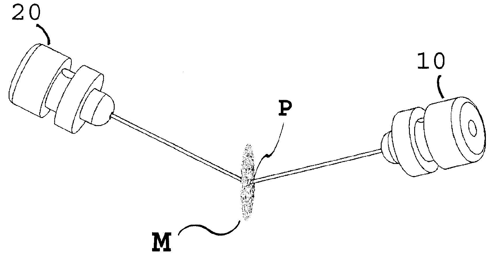
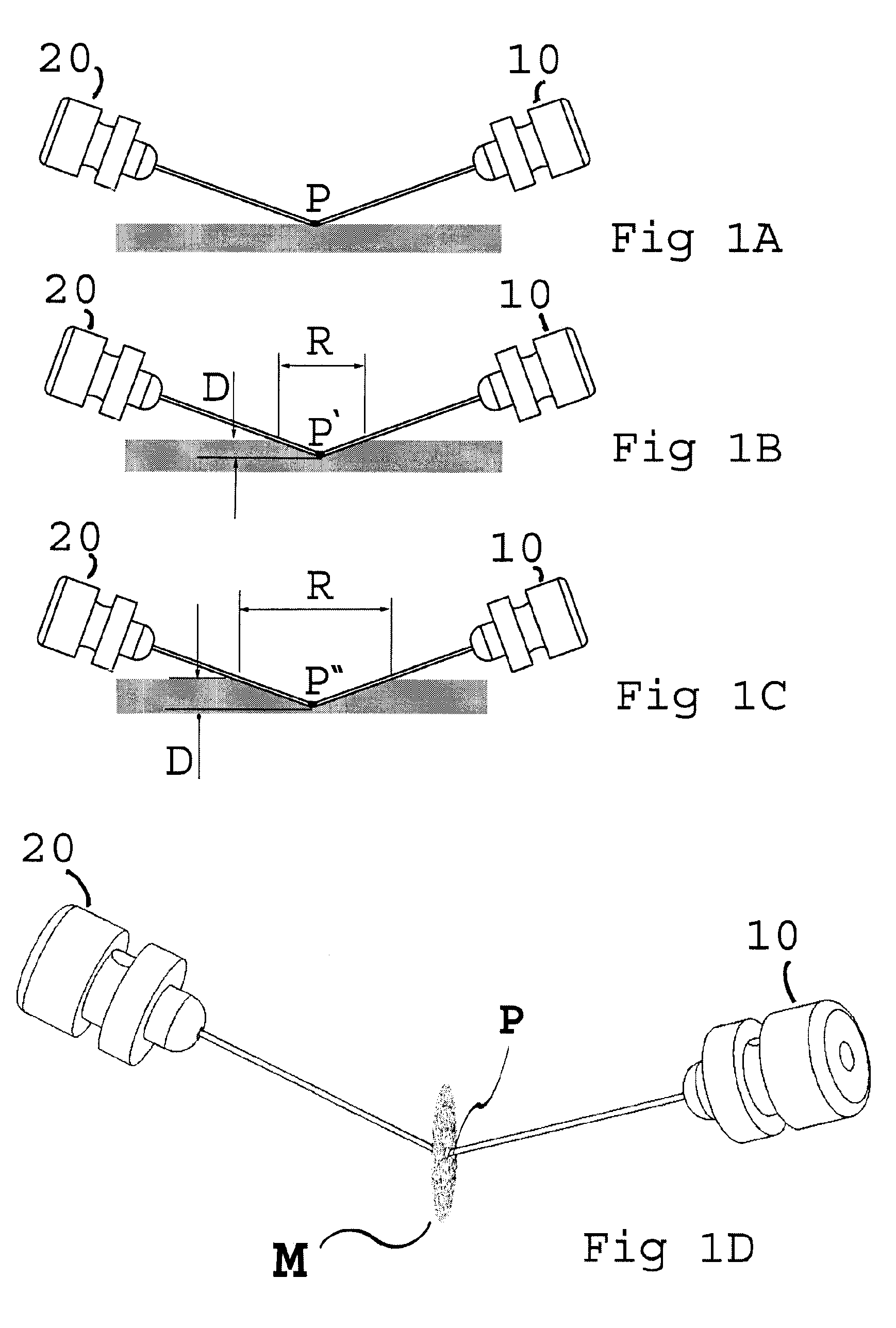
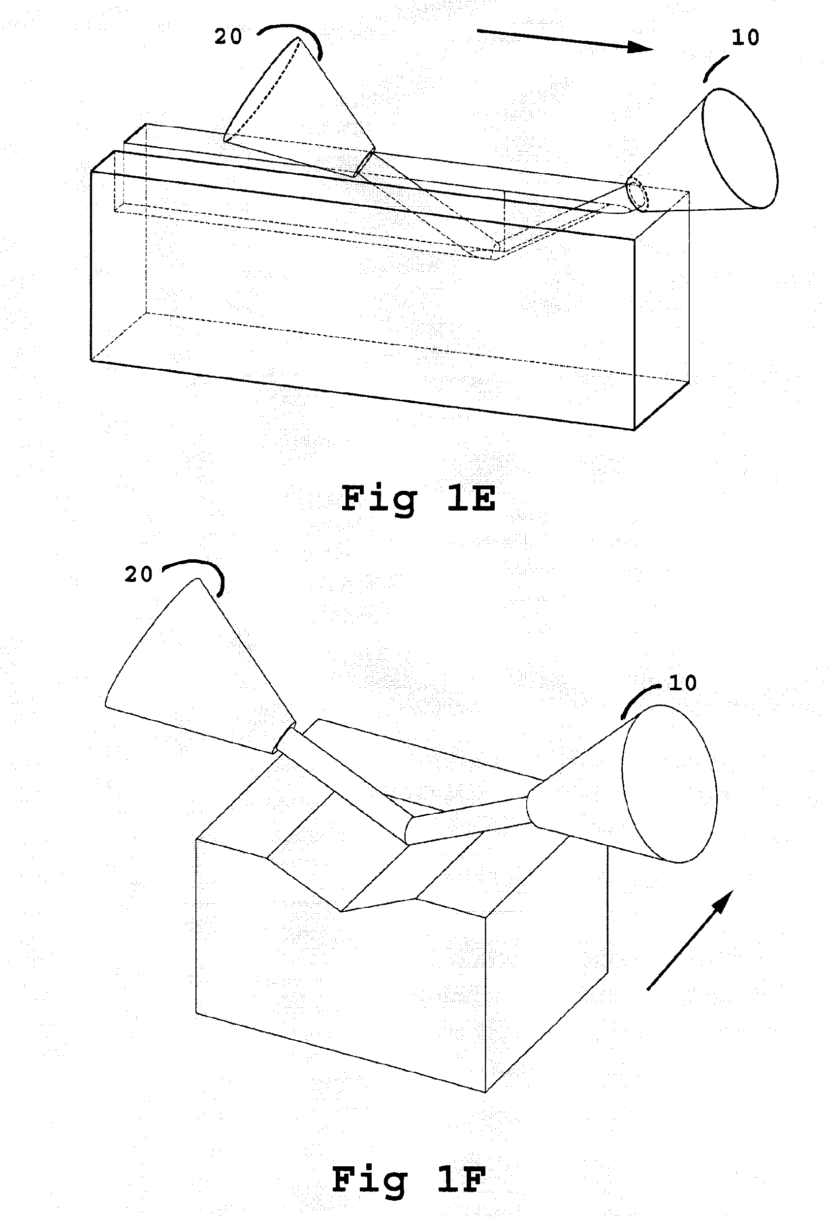
[0081]As in the prior embodiment, the distal end of device 200 in FIGS. 6A-6C contains a jet nozzle dispenser 215 which includes a nozzle assembly comprising two jet nozzles, configured to emit liquid jets. In this embodiment, the plurality of nozzles of the nozzle assembly are distributed evenly in a circle and connected to a pressurized working liquid source. The trajectories of the liquid jets emitted from the nozzles intersect at a point located on an axis “AA” (best seen in FIG. 7A) passing through the center of the circle and normal to the circle's plane. The nozzles are positioned to produce liquid jets ...


PUM

PropertyMeasurementUnit
Depthaaaaaaaaaa
Distanceaaaaaaaaaa

Abstract

A liquid cutting device employing pressurized working liquid which includes a nozzle assembly. The assembly includes a plurality of liquid jet nozzles, each nozzle of which has a nozzle axis. The plurality of nozzles are arranged so that their nozzle axes intersect at an intersection point located at a predetermined distance downstream from the nozzles. The device also includes an apparatus for delivering the pressurized working liquid to the nozzles. Each of the nozzles is configured to selectably emit a liquid jet operative to cut through a target material. The liquid jets emitted from the nozzles interfere and disperse each other when meeting at the intersection point and the liquid jets are atomized. The device includes a spacer element adjustably mounted onto the nozzle assembly, which increases or decreases the cutting depth of the device. A method for employing the liquid cutting device is also discussed.

Description

FIELD OF THE INVENTION[0001]The present invention relates to a liquid cutting device which inter alia is usable for surgical procedures.BACKGROUND OF THE INVENTION[0002]Liquid jets, primarily water jets, have been used in industry for years as the basis for cutting instruments. A water jet cutter is a tool able to slice into various solid materials with the help of a high speed water jet which sometimes may include abrasive materials. The design of water jet cutting devices is simple. Usually, the water pumping system employs ultra-high pressure pumps, which can deliver pressures between about 270 MPa and about 600 MPa. The water or water-abrasive mix exits the nozzle of the device at extremely high speeds. As it impacts the surface of the material that is to be cut, it starts stripping tiny bits of matter away from it, creating what we observe as a cut in the material.[0003]Water jet technology has also been adapted for use in different areas of medicine. It has been found that the...

Claims


Application Information

Patent Timeline
IPC IPC(8): B26F1/00
CPCB24C1/045B24C7/0015B26F3/008B26F3/004B24C9/003Y10T83/0591Y10T83/364
Inventor TAVGER, MICHAEL
Owner TAVGER MICHAEL
Why Eureka
Try Eureka