Method for the manufacture of a composite core for an electrical cable
a technology of aluminum conductors and composite cores, which is applied in the direction of power cables, insulated conductors, cables, etc., can solve the problems of cable sag, many problems, and component limitations of traditional cables
- Summary
- Abstract
- Description
- Claims
- Application Information
AI Technical Summary
Benefits of technology
Problems solved by technology
Method used
Image
Examples
example
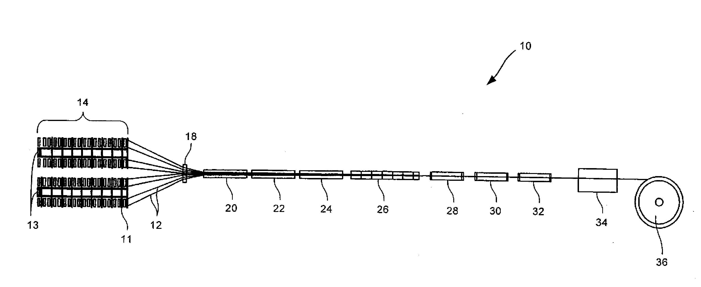
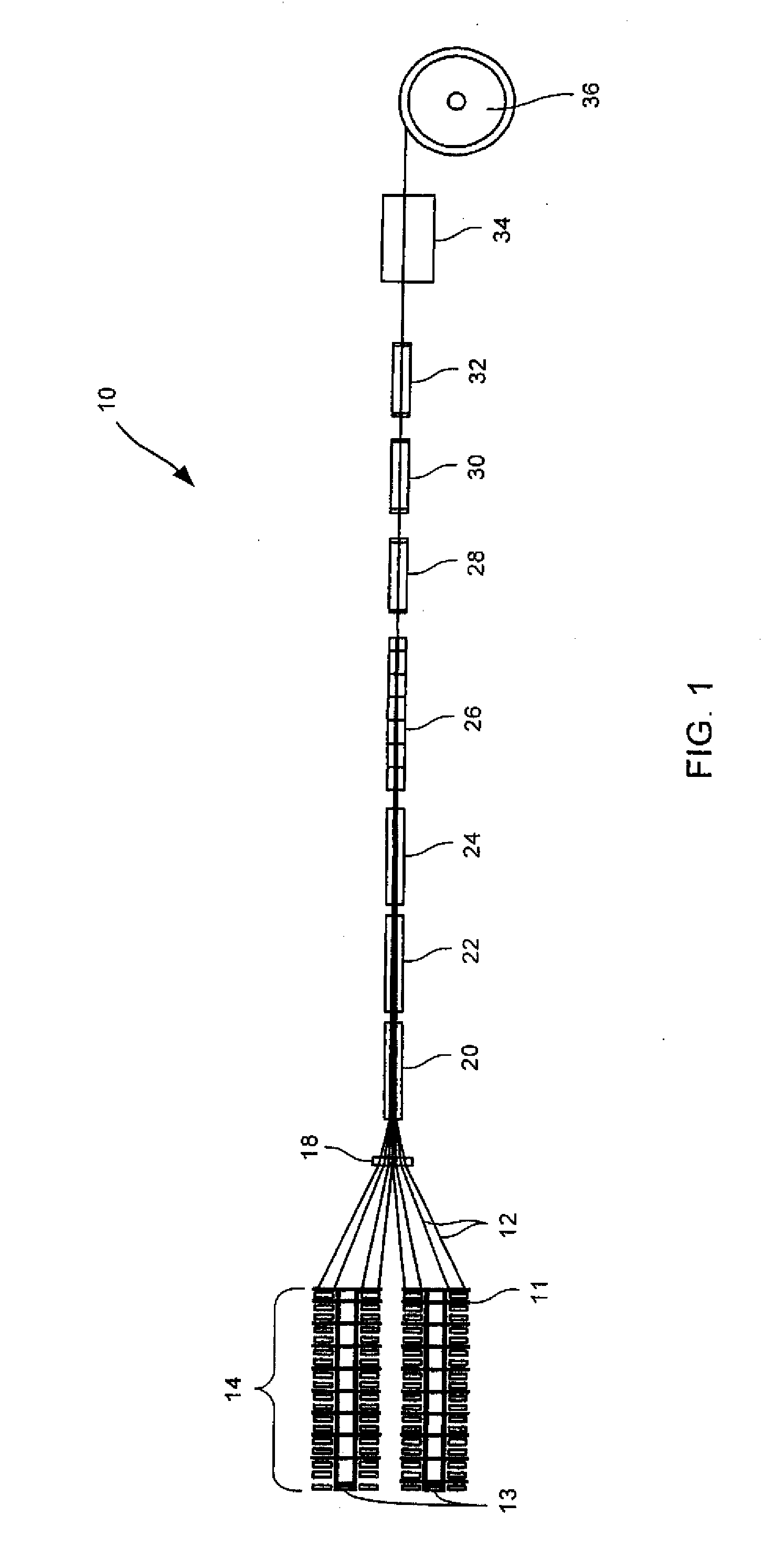
[0109]In accordance with another embodiment of the invention, a multi-phase B-stage forming process produces a composite core member from substantially continuous lengths of suitable fiber tows and heat processable resins. In a further step, the composite core member is wrapped with high conductivity aluminum.
[0110]A process for making composite cores for ACCC cables according to the invention is described as follows. Referring to FIG. 1, the conductor core B-stage forming process of the present invention is shown and designated generally by reference number 10. The B-stage forming process 10 is employed to make continuous lengths of composite core members from suitable fiber tows or rovings and heat processable resins. The resulting composite core member comprises a hybridized concentric core having an inner and outer layer of uniformly distributed substantially parallel fibers.
[0111]In starting the operation, the pulling and winding spool mechanism is activated to commence pulling...
example one
Composite Core
[0173]A particular embodiment of the invention is now described wherein the composite strength member comprises boron free E-glass and carbon with type 13 sizing. E-glass combines the desirable properties of good chemical and heat stability, and good electrical resistance with high strength. The cross-sectional shape or profile is illustrated in FIG. 8 wherein the composite strength member comprises a concentric carbon core encapsulated by a uniform layer of glass fiber composite. In a preferred embodiment the process produces a hybridized core member comprising two different materials.
[0174]The fiber structures in this particular embodiment are 54 ends of E-glass product, 220 yield Veterotex Amer and 28 ends of carbon Torayca T7DOS yield 24K. The resin used is Araldite MY 721 from Vantico.
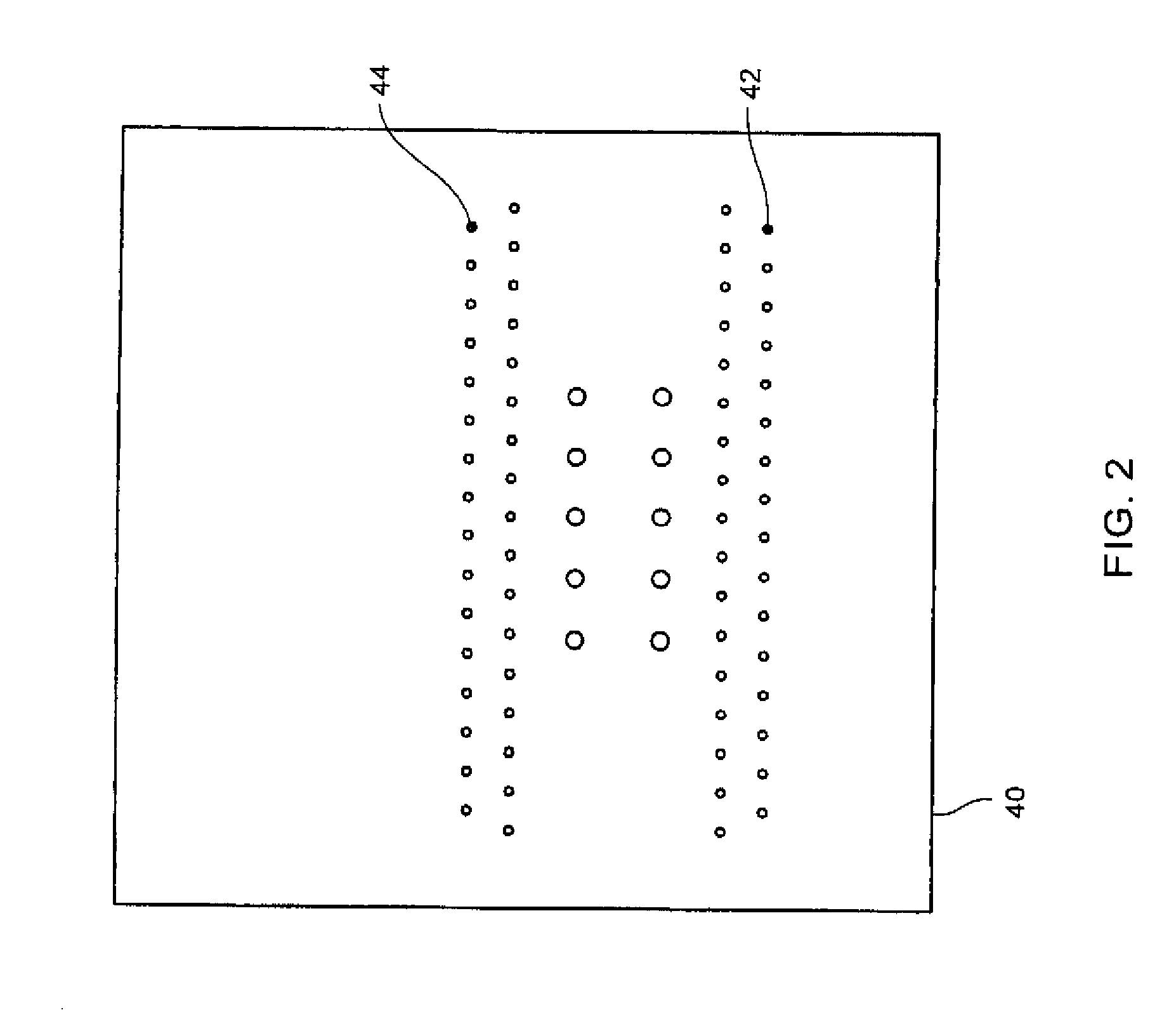
[0175]In operation, the ends of E-glass and carbon are threaded through a fiber tow guide comprising two rows of 32 passageways, two rows inner of 31 passageways and two innermost ro...
example two
Composite Core
[0179]An example of an ACCC reinforced cable in accordance with the present invention follows. An ACCC reinforced cable comprising four layers of components consisting of an inner carbon / epoxy layer, a next glassfiber / epoxy layer and two layers of tetrahedral shaped aluminum strands. The strength member consists of an advanced composite T700S carbon / epoxy having a diameter of about 0.2165 inches, surrounded by an outer layer of R099-688 glassfiber / epoxy having a layer diameter of about 0.375 inches. The glassfiber / epoxy layer is surrounded by an inner layer of nine trapezoidal shaped aluminum strands having a diameter of about 0.7415 inches and an outer layer of thirteen trapezoidal shaped aluminum strands having a diameter of about 1.1080 inches. The total area of carbon is about 0.037 in2, of glass is about 0.074 in2, of inner aluminum is about 0.315 in2 and outer aluminum is about 0.5226 in2. The fiber to resin ratio in the inner carbon strength member is 70 / 30 by w...
PUM
| Property | Measurement | Unit |
|---|---|---|
| viscosity | aaaaa | aaaaa |
| temperature | aaaaa | aaaaa |
| length | aaaaa | aaaaa |
Abstract
Description
Claims
Application Information
 - R&D
- Intellectual Property
- Life Sciences
- Materials
- Tech Scout
- Unparalleled Data Quality
- Higher Quality Content
- 60% Fewer Hallucinations
Browse by: Latest US Patents, China's latest patents, Technical Efficacy Thesaurus, Application Domain, Technology Topic, Popular Technical Reports.
© 2025 PatSnap. All rights reserved.Legal|Privacy policy|Modern Slavery Act Transparency Statement|Sitemap|About US| Contact US: help@patsnap.com


