Cyclonic motor cooling for material handling vehicles

Active Publication Date: 2010-07-22
RAYMOND LTD
View PDF37 Cites 4 Cited by
  • Summary
  • Abstract
  • Description
  • Claims
  • Application Information

AI Technical Summary

Benefits of technology

[0017]Another aspect of the present invention provides a method of operating a material handling vehicle having an operator compartment and a motor compartment with at least one heat generating component inside, the method comprising the steps of enabling operation of the material handling ve

Problems solved by technology

Adding such a footrest, however, is difficult due to the design limitations of crowded operator compartments.
This, however, comes at a cost, namely, reduced motor cooling capacity as explained below.
When housed in a smaller motor compartment, however, the temperature therein rises at much faster rate and quickly overwhelms the capacity of the cooling fans to effectively cool the motors and other heat-generating components located therein.
However, forklifts are typically operated indoors

Method used


Image

  • Cyclonic motor cooling for material handling vehicles
  • Cyclonic motor cooling for material handling vehicles
  • Cyclonic motor cooling for material handling vehicles

Examples


Example

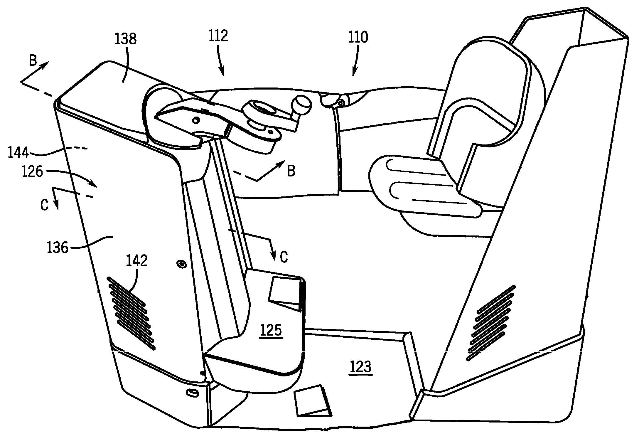
[0031]With specific reference to FIGS. 3-5, a first embodiment of the cyclonic motor cooling system 140 is shown. A number of helical air aligners 158, or alternatively, a continuous helical baffle 158, extend axially upwardly throughout the compartment 126. The helical air aligners 158 extend radially inwardly from the inner surface 145 of the wall 136, at an acute angle Θ, to form spiral cooling air channels 159 therebetween. The spiral channels 159 direct the cooling air vertically towards the exhaust port 144 and help maintain the helical flow path 148 of the cyclonic cooling air.

[0032]A variety of factors are taken into consideration in designing the appropriate air aligner 158 / cooling channel 159 arrangement to ensure that the cyclonic cooling system 140 has the capacity to adequately cool the motor compartment 126. Environmental factors affecting the cooling capacity include the size of the motor compartment 126, amount of heat generated by the motors 30, 32, and the temperat...

Example

[0033]With specific reference to FIG. 6 now, a second embodiment of the cyclonic motor cooling system 240 is shown. The cyclonic cooling system 240 includes an upwardly extending baffle cylinder 160 circumferentially disposed about the inner surface 145 of the motor compartment 126. The baffle cylinder 160 receives the linearly or tangentially directed cooling air from the air injection port 144 and redirects the cooling air circumferentially. The cooling air is deflected axially upwardly as it travels circumferentially through the cylinder 160. The cooling air is given a helical swirling motion as it flows past a number of inclined deflector vanes 162 arranged at the upper end of the baffle cylinder 160.

[0034]Thus, the cyclonic motor cooling systems 140, 240 provide more effective heat removal from motor compartments 126, reducing the need for larger blowers or other types of cooling system, e.g., liquid cooling, for smaller motor compartments 126. Those of ordinary skill in the ar...


PUM


Abstract

A material handling vehicle includes a cyclonic motor cooling system for a motor compartment that accommodates an ergonomically designed operator compartment. Together, the motor compartment and cyclonic motor cooling system include a generally cylindrical housing with a tangentially arranged cooling air injection port at a lower end and exhaust port at a radially and axially opposite end. An air blower directs cooling air into the compartment where a cyclonic cooling air flow and a vortex cooling flow is produced. The cyclonic air flow cools more effectively than conventional linear air flow while also reducing dust contamination and buildup of the motors in the motor compartment.

Description

CROSS-REFERENCE TO RELATED APPLICATIONS[0001]Not applicable.STATEMENT REGARDING FEDERALLY SPONSORED RESEARCH[0002]Not applicable.BACKGROUND OF THE INVENTION[0003]The present invention relates to material handling vehicles, interchangeably referred to herein as “lift trucks”, and more particularly, to a cyclonic motor cooling system for use in motor compartments of material handling vehicles.[0004]Lift trucks are designed for use in various types of environments and applications. Lift trucks are configured to perform functions necessary in a given environment of use or application. Lift truck operator compartments are, in turn, designed to allow the operators to assume an operating position allowing them to perform the required material handling task.[0005]To this end, some lift trucks operator compartments have been designed so that an operator has the option of operating the lift truck in either a standing or a seated position. Operator compartments for these types of lift trucks (...

Claims


Application Information

Patent Timeline
IPC IPC(8): B60K11/00B60H1/00
CPCB66F9/07595
Inventor FIELD, MICHAEL GEORGE
Owner RAYMOND LTD
Why Eureka
Try Eureka