Omnidirectional drive and steering unit

a technology of omnidirectional drive and steering unit, which is applied in the direction of manufacturing tools, process and machine control, instruments, etc., can solve the problems of limiting the amount of load a vehicle can carry and the maneuverability of the vehicle, the top-heavy vehicle, and the limit of the load a vehicle can carry and maneuverability, so as to reduce the space or area necessary for vehicle operation, improve maneuverability, and increase load capability

Active Publication Date: 2010-07-22
BOOMERANG SYST INC
View PDF11 Cites 36 Cited by
  • Summary
  • Abstract
  • Description
  • Claims
  • Application Information

AI Technical Summary

Benefits of technology

[0005]The present invention discloses, in one embodiment, a compact wheel drive and steering system that is preferably placed under a load, or in one example a vehicle, rather than adjacent thereto, and that is capable of rotating a vehicle to any degree around its central vertical axis, and of moving a vehicle in any direction without altering its orientation or that of a load.
[0006]The placement of the system under a vehicle increases the load capability, and the omnidirectional nature of the drive and steering system improves maneuverability and reduces the space or area necessary for vehicle operation. For example, an AGV equipped with one or more omnidirectional steering and drive units of the present invention working in a coordinated fashion, operating in an automated parking facility, can slide under an automobile because of the placement and compactness of the drive and steering units, lift the automobile and turn around without using a turntable or making a U-turn in an arc, travel for a distance and deposit the automobile in a storage space or aisle that is normal to the direction of the vehicle without changing the orientation of the vehicle or using ...

Problems solved by technology

That design simplifies the mechanical components of the system, but limits the amount of the load a vehicle can carry and the maneuverability of the vehicle.
The load is limited because the placement of the drive and steering components adjacent to the load increase...

Method used


Image

  • Omnidirectional drive and steering unit
  • Omnidirectional drive and steering unit
  • Omnidirectional drive and steering unit

Examples


Embodiment Construction

[0027]This disclosure describes the best mode or modes of practicing the invention as presently contemplated. This description is not intended to be understood in a limiting sense, but provides an example of the invention presented solely for illustrative purposes by reference to the accompanying drawings to advise one of ordinary skill in the art of the advantages and construction of the invention. In the various views of the drawings, like reference characters designate like or similar parts.

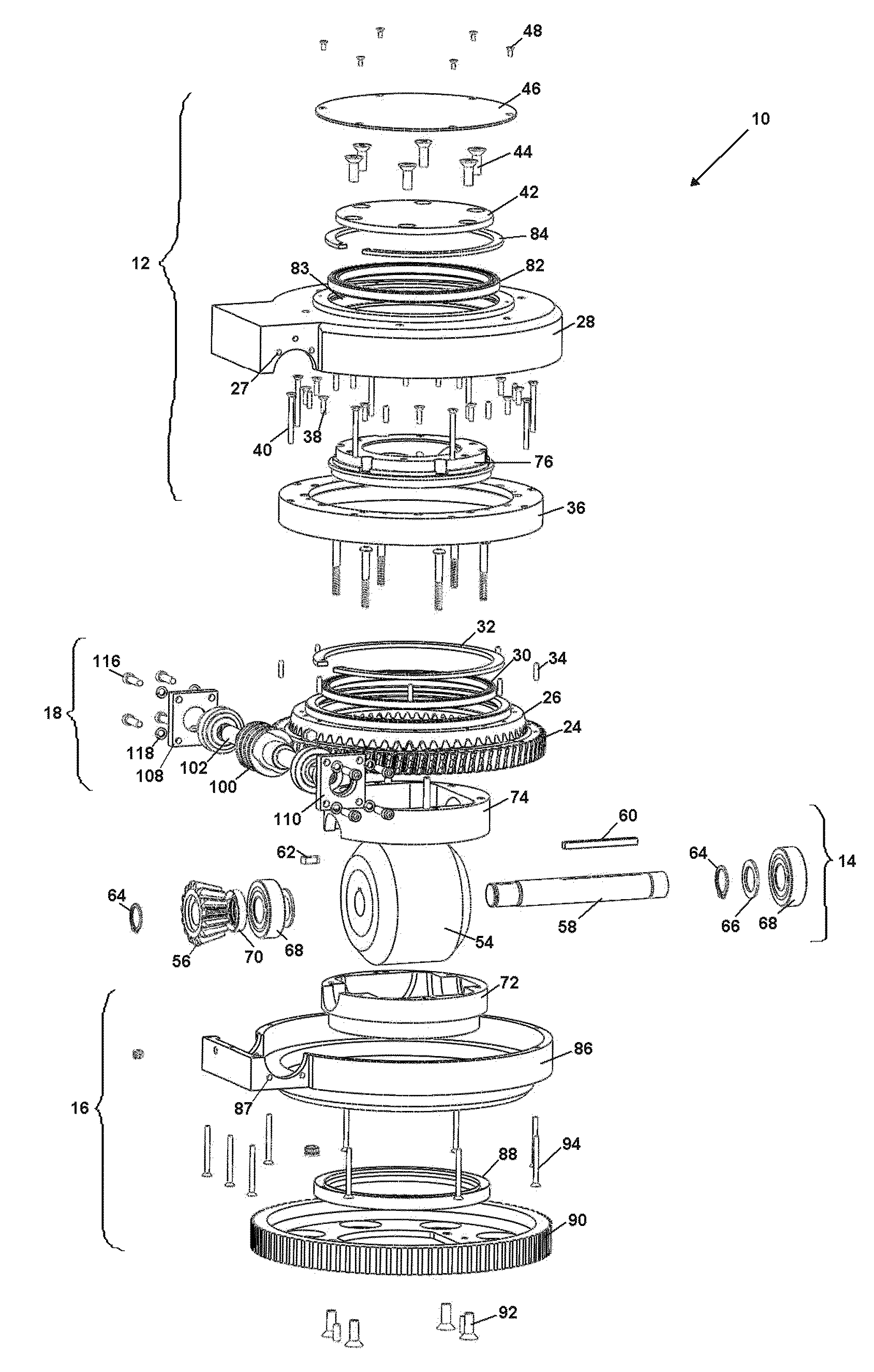
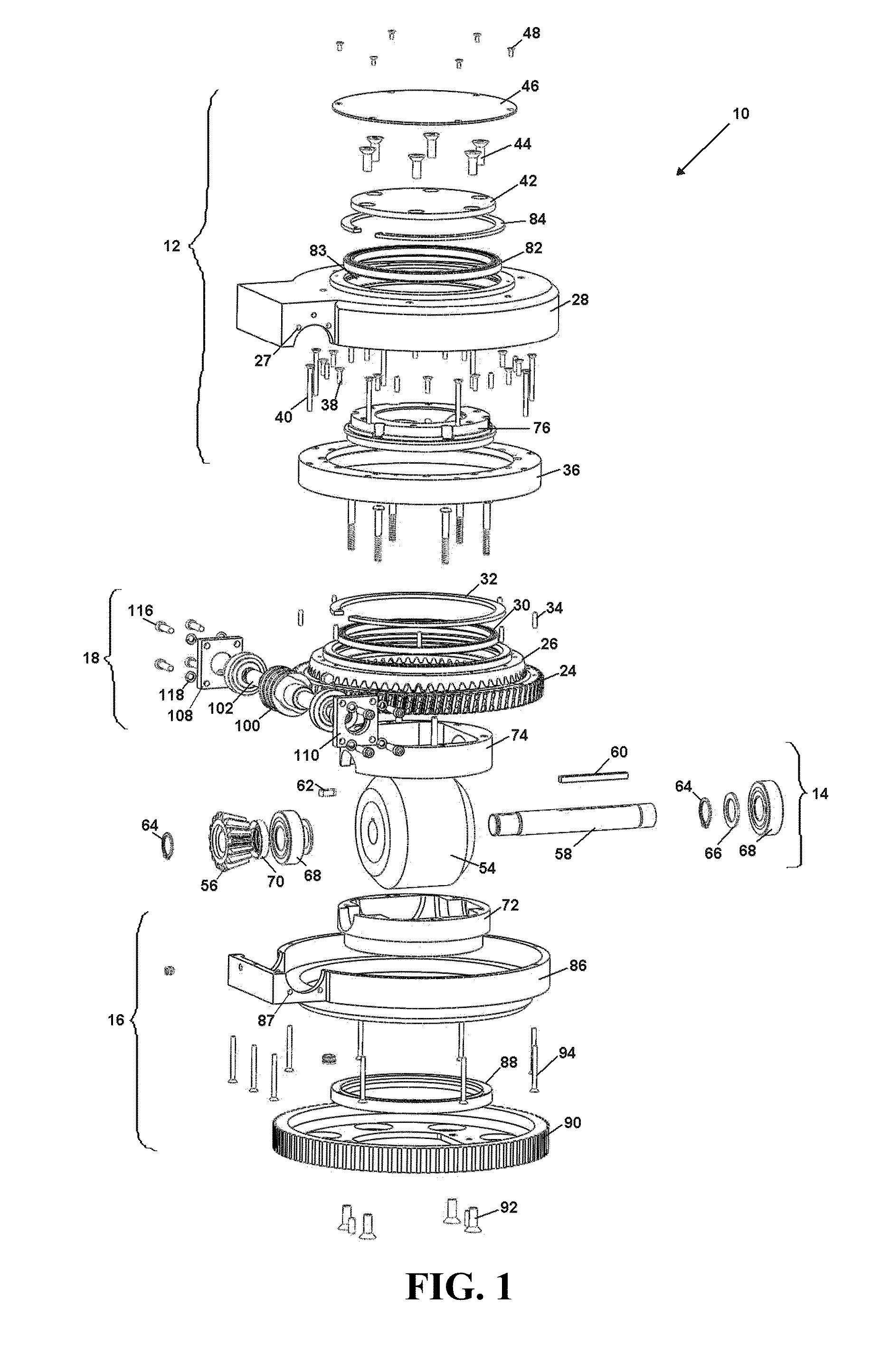
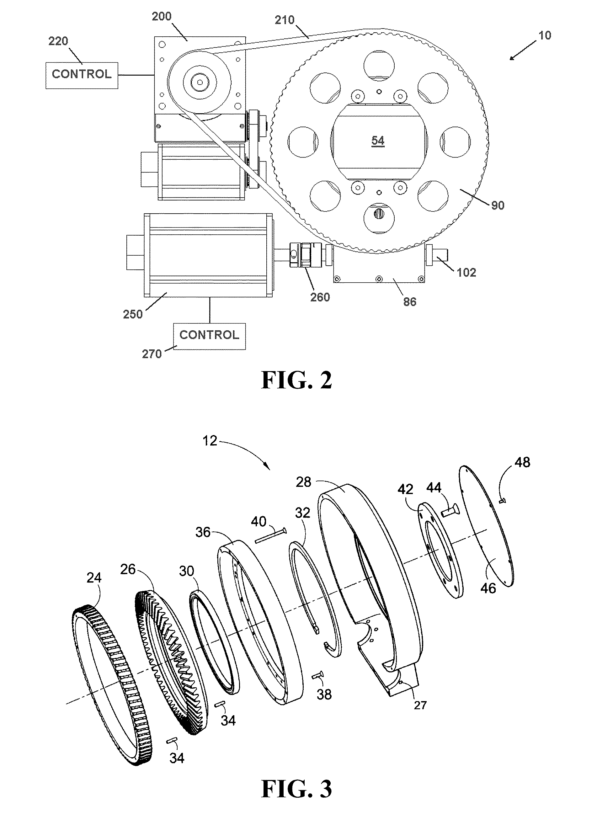
[0028]FIG. 1 is an exploded view of one embodiment of an omnidirectional drive and steering unit 10 (hereinafter referred to as unit 10) generally comprising an upper case assembly 12, a lower case assembly 16, a wheel housing assembly 14 enclosing a wheel 54, and a drive assembly 18. One embodiment of a method of assembly of each generally-referenced region is further illustrated in the figures that follow, where FIG. 3 illustrates one embodiment of an assembly of the upper case assembly 12, ...


PUM

PropertyMeasurementUnit
Angleaaaaaaaaaa
Diameteraaaaaaaaaa

Abstract

A compact, low profile omnidirectional drive and steering unit that, in one embodiment, utilizes a single, centrally located wheel, mounted on a drive shaft, upon which is also mounted a tapered pinion gear. The pinion gear on the drive shaft meshes with a ring shaped beveled worm gear contained within the outer housing of the gear unit that surrounds the centrally located wheel. At one side of the outer housing is a worm drive that meshes with the ring shaped and beveled worm gear. Rotation of the worm drive causes rotation of the ring shaped worm gear, which causes the drive shaft mounted pinion gear to turn, which turns the drive wheel to provide driving power for whatever vehicle or system of which the unit is a part. A steering and timing gear is mounted on the lower surface of the unit to provide steering capability.

Description

CROSS-REFERENCE TO RELATED APPLICATIONS[0001]This application claims the benefit of U.S. Application 61 / 145,543, filed Jan. 17, 2009, U.S. Application 61 / 248,448, filed Oct. 3, 2009, and U.S. Application 61 / 258,006, filed Nov. 4, 2009, the contents of each of which are incorporated herein by reference.FIELD OF THE INVENTION[0002]The present invention relates to a wheel drive and steering unit for, in one embodiment, automatic guided vehicles (AGVs) and other semi-automatic or manually controlled vehicles. More particularly, the present invention relates to a compact and low profile drive and steering unit that has a unique ability to fully rotate a vehicle around its central vertical axis, and to drive or move a vehicle in any direction without altering the orientation of the vehicle.BACKGROUND OF THE INVENTION[0003]Conventional AGVs rely upon gear units that house separate drive and steering components that are adjacent to a load carried by a vehicle. For example, conventional AGVs...

Claims


Application Information

Patent Timeline
IPC IPC(8): B60K17/30B23P11/00
CPCB60K17/30B62D5/0418B62D7/026Y10T29/49826G05D2201/0216E04H6/00G05D1/0297G05D1/0265E04H6/183E04H6/245E04H6/305E04H6/36
Inventor SWASEY, MERIN J.CHECKETTS, STANLEY J.
Owner BOOMERANG SYST INC
Why Eureka
Try Eureka