Optical tomographic imaging apparatus

a tomographic imaging and optical technology, applied in the field of optical tomographic imaging apparatus, can solve the problems of the above-mentioned optical apparatus, which is a conventional example, and achieve the effect of increasing the influence of aberration and individual variation of the biological optical system of the human ey

Inactive Publication Date: 2010-07-22
CANON KK
View PDF5 Cites 25 Cited by
  • Summary
  • Abstract
  • Description
  • Claims
  • Application Information

AI Technical Summary

Benefits of technology

[0066]However, if the beams diameter is increased, the individual variation of the biological optical systems of human eyes is further increased. This is because an influence of the aberration incr

Problems solved by technology

However, the OCT apparatus described above as a conventional example has problems as follows.
However, Japanese Patent Application Laid-Open No. 2007-101250 does not disclose anything about performing the serial jobs regarding the zone f

Method used


Image

  • Optical tomographic imaging apparatus
  • Optical tomographic imaging apparatus
  • Optical tomographic imaging apparatus

Examples


Embodiment Construction

[0093]Next, an optical tomographic imaging apparatus according to an embodiment of the present invention is described.

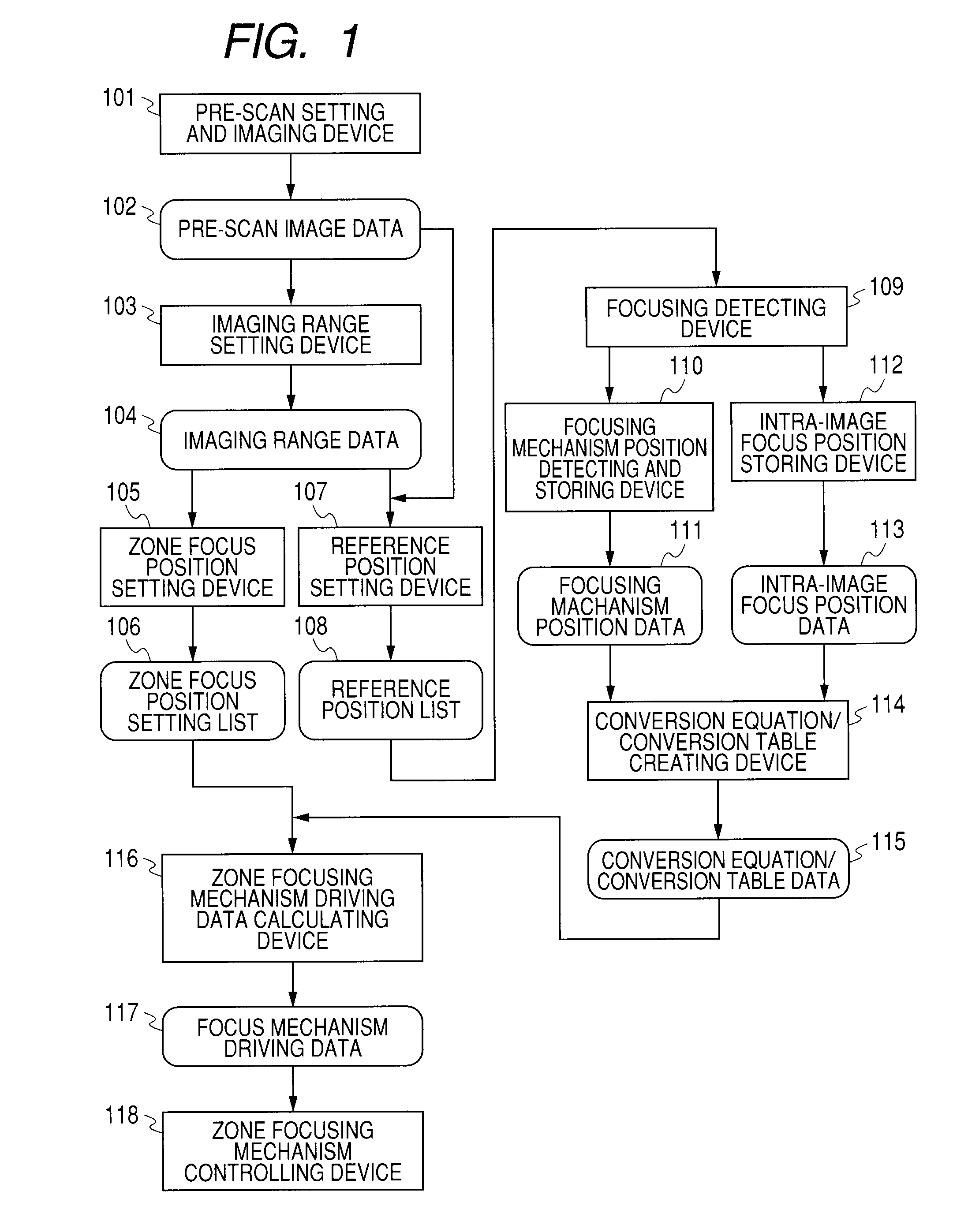
[0094]FIG. 1 is a schematic block diagram illustrating an overall function of a structural example of the optical tomographic imaging apparatus according to this embodiment.

[0095]In the optical tomographic imaging apparatus of this embodiment, a pre-scan setting and imaging device 101 performs pre-scan so that pre-scan image data 102 is obtained.

[0096]In the pre-scan, a reference beams delay position and a focus position are set roughly.

[0097]In other words, setting for obtaining an optimized image is not necessary as long as a profile image of an entire object can be obtained.

[0098]For instance, the pre-scan is performed after searching manually by an operator for a reference beams delay position and a focus position for obtaining a rough image.

[0099]Alternatively, one A-scan may be obtained automatically, before searching for a reference beams delay position having...


PUM


Abstract

Provided is an optical tomographic imaging apparatus that is capable of shortening a period of time of focusing at multiple focus positions when images split in a depth direction are obtained by zone focusing. The optical tomographic imaging apparatus includes: a focus position setting device for splitting a zone within a predetermined imaging depth range into multiple focus zones so as to set multiple focus positions; a reference position setting device for setting at least two reference positions in an imaging depth direction within the predetermined imaging depth range; and a focus controlling device for performing focusing at the multiple focus positions sequentially based on focus position information generated by the focus position setting device and determining a focus condition of an in-focus state for the at least two reference positions set in advance by the reference position setting device.

Description

BACKGROUND OF THE INVENTION[0001]1. Field of the Invention[0002]The present invention relates to an optical tomographic imaging apparatus, and more particularly, to an optical tomographic imaging apparatus that is used for opthalmological care, tomographic observation of skin, tomography scan of a digestive and cardiovascular wall with an endoscope or a catheter constituted of the optical tomographic imaging apparatus, or the like.[0003]2. Description of the Related Art[0004]In recent years, an optical interference tomographic imaging method and an optical interference tomographic imaging apparatus, to which a low coherence interferometer technology or a white light interferometer technology is applied, are in actual use.[0005]In particular, an optical tomographic imaging apparatus (optical interference tomographic imaging apparatus) that performs an optical coherence tomography (OCT) utilizing interference phenomenon of multi-wavelength light may be used to obtain a tomographic ima...

Claims


Application Information

Patent Timeline
IPC IPC(8): G01B9/023
CPCG01B9/02044G01B9/02048G01B9/02063G01B9/02091A61B3/102
Inventor SUGITA, MITSURO
Owner CANON KK
Why Eureka
Try Eureka