Threaded joint with resilient seal ring

a technology of resilient seals and threaded joints, which is applied in the direction of screw threaded joints, hose connections, mechanical equipment, etc., can solve the problems of destroying the original seal o-ring and the need for a new seal ring for new make-up, so as to reduce the operative cost in time and tasks, increase the cost, and the effect of easy making

Active Publication Date: 2010-07-22
TENARIS CONNECTIONS
View PDF106 Cites 20 Cited by
  • Summary
  • Abstract
  • Description
  • Claims
  • Application Information

AI Technical Summary

Benefits of technology

[0019]The advantage of the invention is to provide a threaded joint reliable in real field operative conditions, where reliability is crucial and reduction in operative costs in terms of time and tasks are desirable.
[0020]The housing for the seal ring of the joint is configured to match in the best manner the shape of the seal ring, and vice versa, whereby the seal ring works synergistically with the housing both during and after make up.
[0021]Advantageously, this synergy is obtained without increasing costs since the groove of the invention is easy to make and is not more complex or expensive to produce than the currently used groove configurations, which house standard O-rings of circular cross-section. In addition the simple shape of the housing cross-section combined with that of the seal ring reduces the overall dimensions of the groove when compared to the dimensions of those grooves for O-rings of circular cross-section since the diameter of the circular cross-section determines the depth of the groove. As is explicatory shown in FIG. 1, which represents two standard O-rings mounted on state of the art joints, since an O-ring of large diameter would be preferable to avoid getting stuck between two adjacent crests of the pin thread during make up, this entails machining a deeper groove (example on the right), and the thickness of the wall w of the box in that portion would be significantly reduced as well as joint wall strength compared to an O-ring of smaller diameter (left example) which entails a wall thickness w′.
[0022]Advantageously a coating can be applied to the surfaces involved by the seal ring for protecting the machined surface of the pin close to the vanishing thread region of the joint which is likely to be exposed to contact by corrosive external agents.

Problems solved by technology

In contrast, after break-out most prior art threaded joints, incorporating well-known O-rings with circular cross-section, damage the original O-ring and a new seal ring must be used for the new make up operation, because the original one has been damaged both by the first make up and by break-out.

Method used


Image

  • Threaded joint with resilient seal ring
  • Threaded joint with resilient seal ring
  • Threaded joint with resilient seal ring

Examples


Embodiment Construction

[0028]With particular reference to the FIGS. 1A to 3, there is shown a threaded joint indicated overall by reference numeral 1, connecting two tubes, a male tube, commonly called a pin 2, with a nominal external diameter D, and a female tube also called a box 3, of external diameter D1, equal to or greater than D.

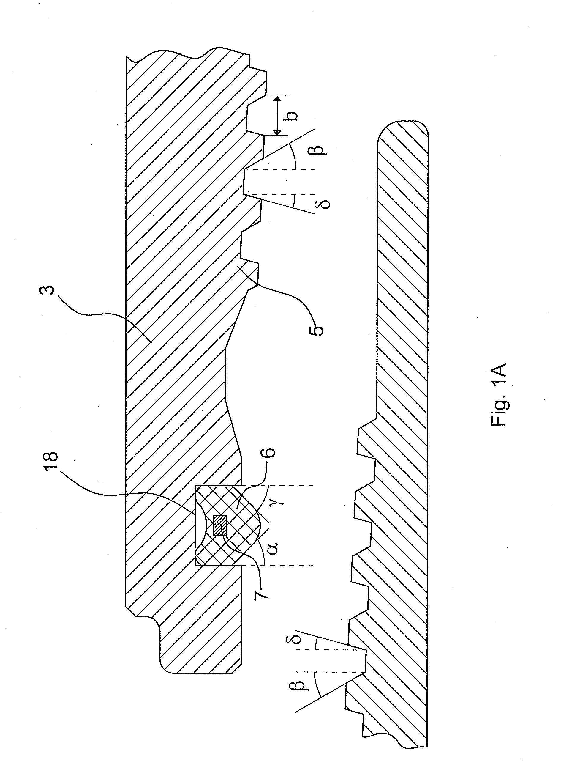
[0029]The pin 2 has a threaded portion 4 with male threads of appropriate profile, e.g. trapezoidal, and the box 3 has an internal threaded portion 5 with female threads.

[0030]The common axis of the pin 2 and box 3 is indicated with A. The box ends with a nose 15.

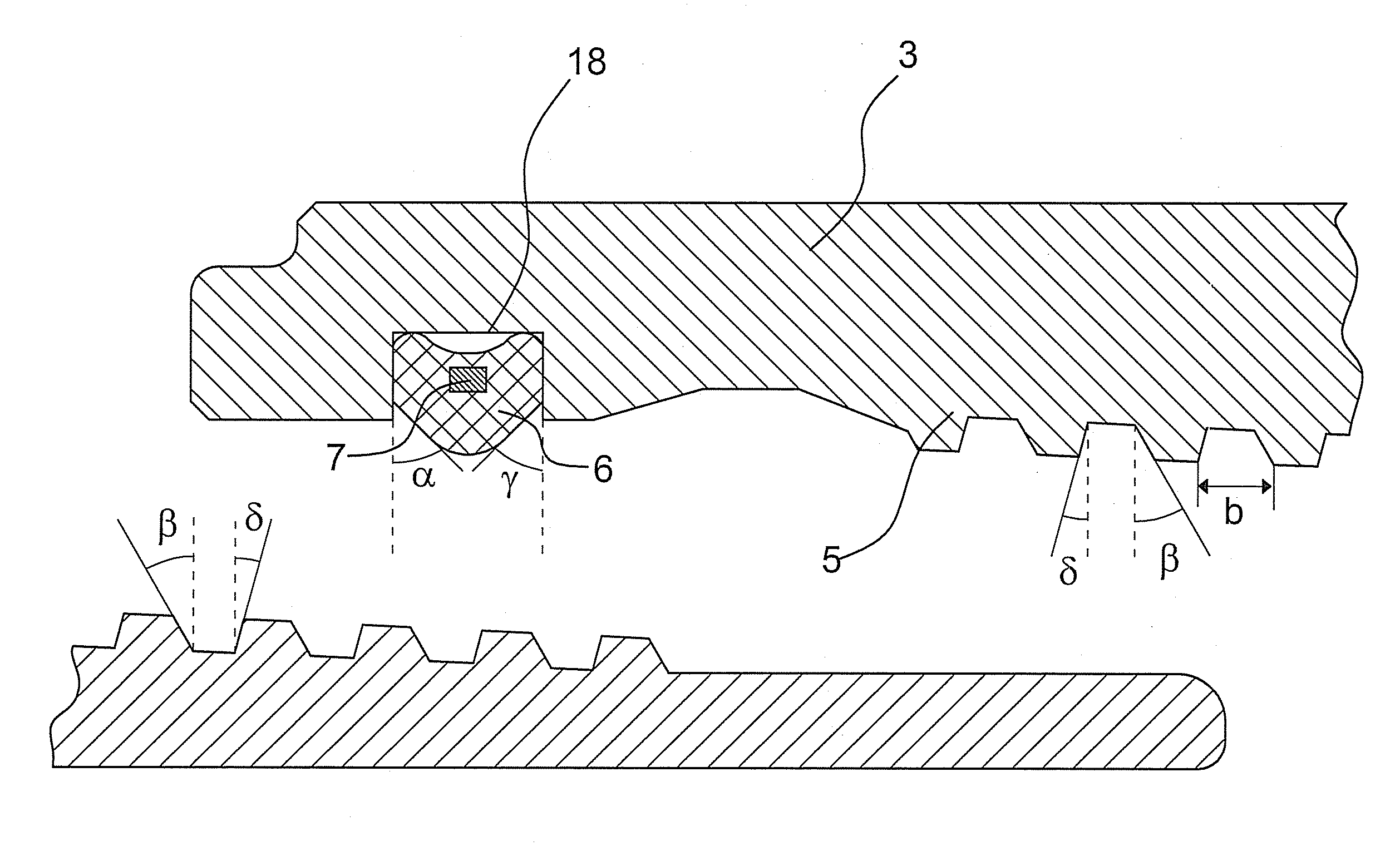
[0031]The portion of the box 3 near the end of the thread 5 comprises an annular groove 18 between box nose 15 and the thread end. This groove 18 is the housing of a seal ring 6.

[0032]With particular reference to FIG. 3, which shows a section of the ring 6 in the unloaded position located in its housing 18 in the box 3, the seal ring 6 has an external surface with two annular ribs 11, 12 separated by an annular fur...


PUM


Abstract

A threaded joint comprises a seal ring positioned between a pin and a box, and located in a groove between the end of a threaded section and the nose of the box. The seal ring has a first base, a second base axially opposite to the first base, at least two protruding annular ribs on the external surface, and an internal surface comprising, in an unloaded position, two frustoconical annular surfaces tapering towards the center of the seal ring and joined by a fillet.

Description

FIELD OF THE INVENTION[0001]The present invention relates to threaded joints, in particular for connecting tubes of predefined length to make strings used in the hydrocarbon industry especially for use in the field of OCTG (Oil Country Tubular Goods) and in line pipes in offshore applications.BACKGROUND OF THE INVENTION[0002]Searching for oil or, more generally, hydrocarbons has become more demanding in terms of hardware and devices in recent years because oil and gas fields or reservoirs are located deeper under the earth's surface or in places difficult to reach below the sea bed. Prospecting for and exploitation of hydrocarbon fields demands hardware which is more resistant to environmental challenges such as higher loads and corrosion, which were less important in the past.[0003]Modern joints are generally designed with metal to metal seals made by the contact between two surfaces, usually at one end or at both ends of the threaded portion of the joint, interfering in the elasti...

Claims


Application Information

Patent Timeline
Patent Type & Authority Applications(United States)
IPC IPC(8): F16L25/00
CPCE21B17/042F16L15/003
Inventor SANTI, NESTOR J.MAZZAFERRO, GASTON
Owner TENARIS CONNECTIONS
Why Eureka
Try Eureka