Pmdc motor

a permanent magnet direct current and commutator motor technology, applied in the direction of dynamo-electric machines, electrical equipment, supports/enclosements/casings, etc., can solve the problems of emc) components, insufficient space left for mounting other components, and components performance reduction

Inactive Publication Date: 2010-07-22
JOHNSON ELECTRIC SA
View PDF6 Cites 32 Cited by
  • Summary
  • Abstract
  • Description
  • Claims
  • Application Information

AI Technical Summary

Benefits of technology

[0007]Preferably, the rotor comprises: a shaft having a first end supported by a bearing held by the end cap; and a ring magnet mounted onto the first end of the shaft; and wherein a PCB is mounted adjacent to the end cap and at least one Hall sensor is mounted on the PCB and arranged to detect rotation of the ring magnet.

Problems solved by technology

The brushes and the chokes are laid on an inner end surface of the end cap, resulting in that there is not enough space left for mounting other components such as electromagnetic compatibility (EMC) components and overcurrent protection components.
However, performance of the components is reduced because the components are farther away from the armature windings.

Method used


Image

  • Pmdc motor
  • Pmdc motor
  • Pmdc motor

Examples


Embodiment Construction

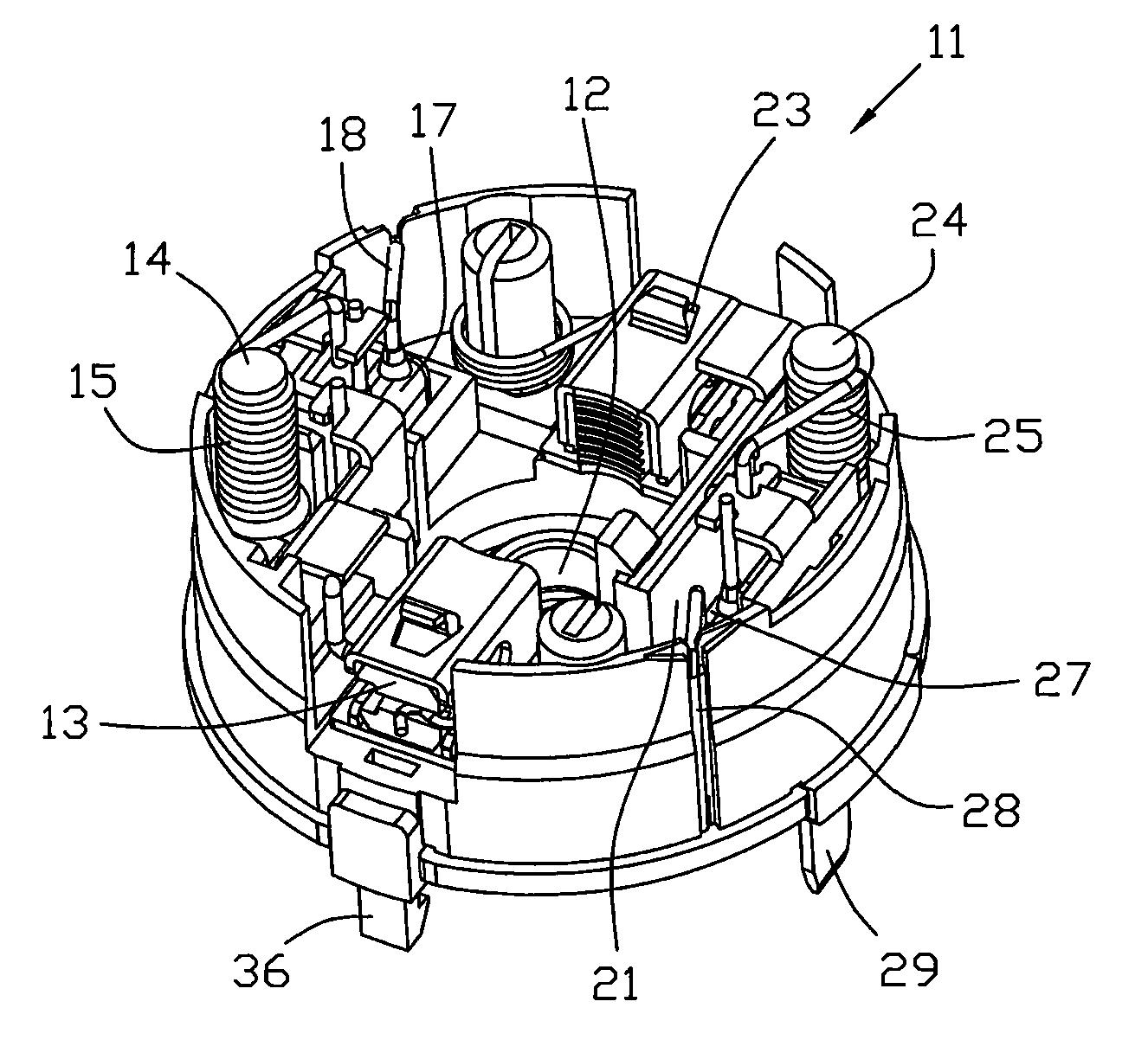
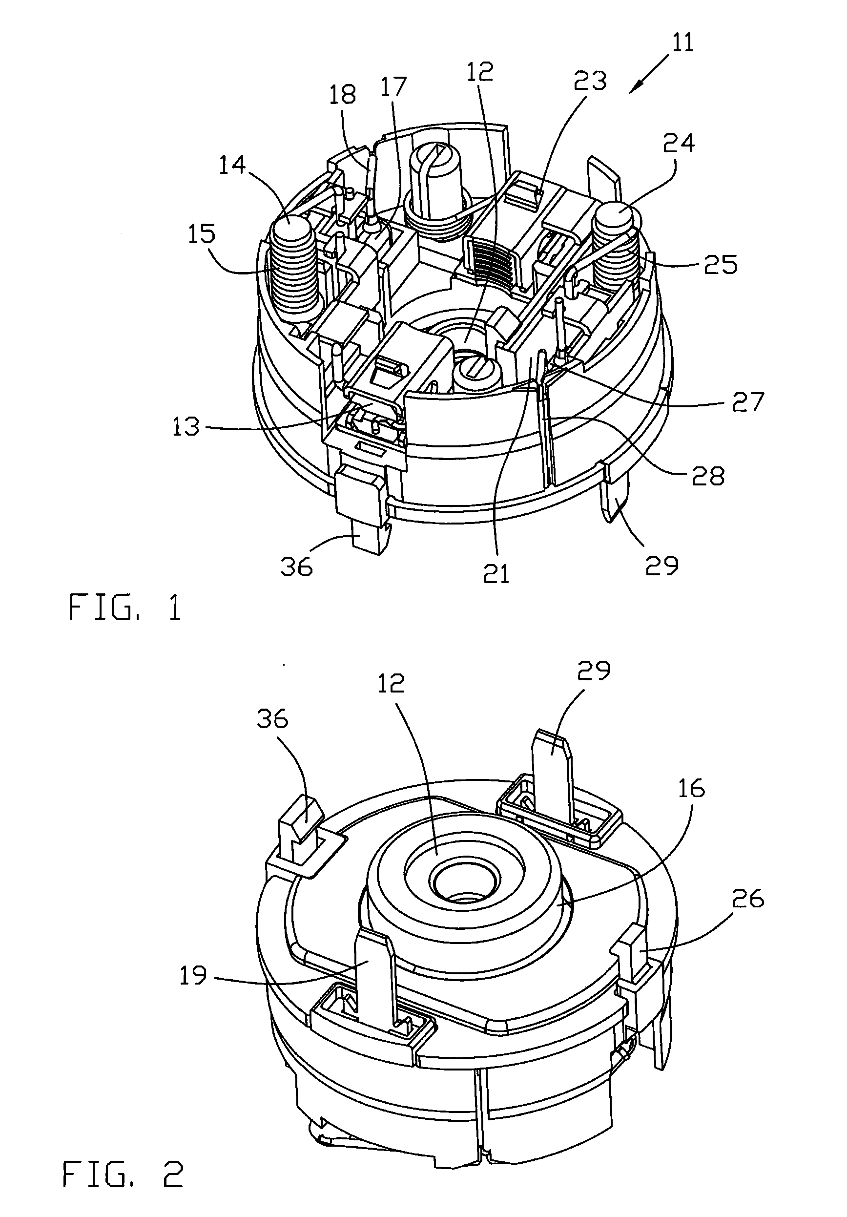
[0026]FIG. 1 and FIG. 2 illustrate an end cap of a PMDC motor according to the preferred embodiment of the present invention. The end cap 11 comprises: a bearing holder 16 for holding a bearing 12, a first brush 13 and a second brush 23 for sliding contact with a commutator (not shown), a first choke 15, a second choke 25, a first terminal 19, a second terminal 29, and a positive temperature coefficient (PTC) thermistor 21. The first brush 13, the first choke 15 and the first terminal 19 are connected in series, while the second brush 23, the second choke 25, the PTC thermistor 21 and the second terminal 29 are connected in series.

[0027]The end cap 11 also comprises a set of capacitors which includes a first capacitor 17 and a second capacitor 27. One lead of the first capacitor 17 is connected to the first terminal 19 and the other lead 18 of the first capacitor 17 is disposed at a circumferential surface of the end cap 11 so that the lead 18 will be electrically connected to the m...


PUM


Abstract

A PMDC motor, particularly for driving an automobile liftgate, comprises a stator and a rotor rotatably mounted to the stator. The stator comprises a housing and an end cap mounted to one end of the housing. The end cap comprises: a first brush, a second brush, a first terminal, a second terminal, a first choke connected in series with the first brush and the first terminal, a second choke connected in series with the second brush and the second terminal, an overcurrent protection component connected in series with the second brush, and a set of capacitors. Each of the chokes comprises an inductor core extending axially and a winding wound about the inductor core.

Description

CROSS REFERENCE TO RELATED APPLICATIONS[0001]This non-provisional patent application claims priority under 35 U.S.C. §119(a) from Patent Application No. 200910105142.3 filed in The People's Republic of China on Jan. 19, 2009.FIELD OF THE INVENTION[0002]This invention relates to a permanent magnet direct current (PMDC) commutator motor, especially such a motor for raising and lowering a liftgate of a vehicle.BACKGROUND OF THE INVENTION[0003]PMDC motors are well-known and have many uses. A PMDC motor generally comprises a stator and a rotor. The stator comprises a housing, permanent magnets fixed onto an inner surface of the housing and an end cap closing an open end of the housing. The rotor comprises: a shaft, a rotor core fixed onto the shaft, a commutator fixed onto the shaft adjacent one end of the rotor core and windings wound about teeth of the rotor core and terminated on segments of the commutator. The rotor is mounted with the rotor core confronting the permanent magnets and...

Claims


Application Information

Patent Timeline
Patent Type & Authority Applications(United States)
IPC IPC(8): H02K11/02H02K11/00
CPCH02K5/225H02K11/0021H02K23/66H02K11/026H02K11/0047H02K11/215H02K11/25
Inventor WONG, BEN TO FANZHANG, HONG WEI
Owner JOHNSON ELECTRIC SA
Why Eureka
Try Eureka