
Image compressing method, image compressing apparatus and image forming apparatus

a compression method and compression technology, applied in the direction of electrical devices, instruments, computing, etc., can solve the problems of insufficient file size attained after compression, complicated processing, and difficulty in improving the compression ratio by employing this technique, etc., to achieve the effect of suppressing large degradation of image quality and high quality

Active Publication Date: 2010-07-22
SHARP KK
View PDF10 Cites 21 Cited by
  • Summary
  • Abstract
  • Description
  • Claims
  • Application Information

AI Technical Summary

Benefits of technology

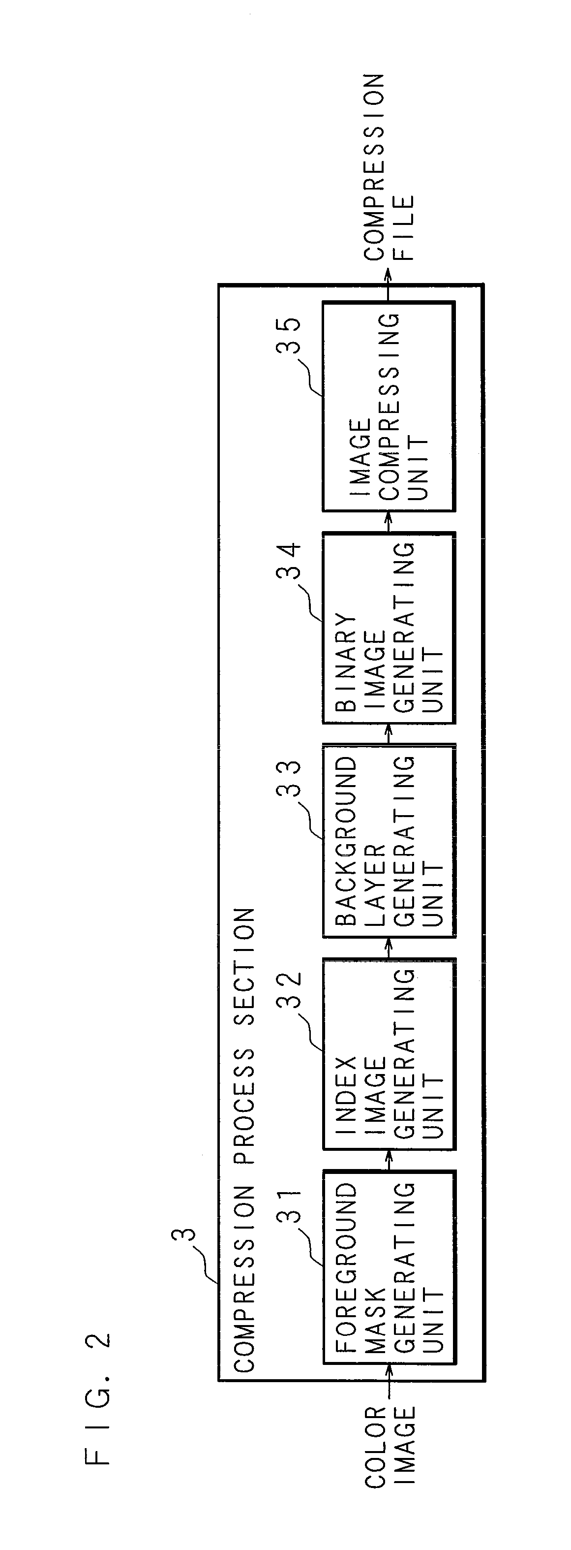
[0009]In a conventionally proposed image compressing apparatus, a foreground layer separated from a color image is further separated before subjecting it to the lossless compression, and thus, the compression ratio can be improved as compared with the case where the foreground layer is directly subjected to the lossless compression. In this image compressing apparatus, one foreground layer is generated by replacing colors of a foreground of one color image with N kinds of identifiers, the generated foreground layer is separated into N binary images respectively corresponding to the N kinds of identifiers, and the separated binary images are individually subjected to the lossless compression. At this point, N is a natural number.
[0010]In the case where the number N of kinds of identifiers is large, the number of binary images to be subjected to the lossless compression is large, and hence, there arises a problem that the file size attained after the compression cannot be sufficiently small. In order to solve this problem, when colors correlated to different identifiers are similar to each other, these colors may be regarded as the same color to be correlated to the same identifier (namely, the different identifiers may be merged), so as to reduce the number of kinds of identifiers. Specifically, an image encoding apparatus working as follows has been proposed (see Japanese Patent Application Laid-Open No. 2003-309727): Color gravity values of color information correlated to different identifiers are compared with each other so as to determine whether or not colors expressed by these color information are similar to each other, and when they are determined to be similar to each other, the compared color information are merged to each other, and the identifiers correlated to these color information are also merged.

Problems solved by technology

On the contrary, since the compression ratio is difficult to control in the lossless compression technique, it is difficult to improve the compression ratio by employing this technique.
In the case where the number N of kinds of identifiers is large, the number of binary images to be subjected to the lossless compression is large, and hence, there arises a problem that the file size attained after the compression cannot be sufficiently small.
As a result, there arises a problem that a text in an achromatic color (or a chromatic color) before the compression is changed in color to a chromatic color (or an achromatic color) through the compression.
If the foreground mask generated by the foreground mask generating means is to be affected by the result of replacement of identifiers performed by the number reducing means, necessary processing is complicated.
If the number of kinds of foreground identifiers corresponding to chromatic colors is excessively large, it is apprehended that the resultant image quality may be degraded.
If the number of kinds of foreground identifiers corresponding to achromatic colors is excessively large, it is apprehended that the resultant image quality may be degraded.

Method used


Image

  • Image compressing method, image compressing apparatus and image forming apparatus
  • Image compressing method, image compressing apparatus and image forming apparatus
  • Image compressing method, image compressing apparatus and image forming apparatus

Examples


embodiment 1

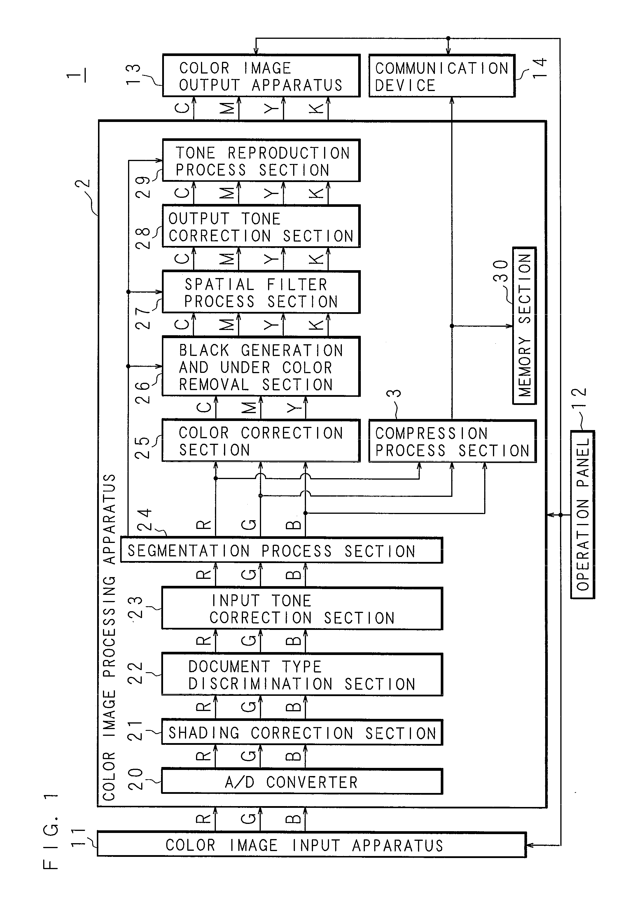
[0089]The present embodiment exemplarily describes an image compressing apparatus included as a part in an image forming apparatus. FIG. 1 is a block diagram illustrating the internal functional configuration of an image forming apparatus 1 according to Embodiment 1 of the invention. The image forming apparatus 1 is a digital multi-function printer having a color copier function, a color scanner function and the like. The image forming apparatus 1 includes a color image input apparatus 11 for optically reading a color image from a document.

[0090]The color image input apparatus 11 is connected to a color image processing apparatus 2 for generating image data and a compression file of the read color image. The color image processing apparatus 2 is connected to a color image output apparatus 13 for outputting a color image on the basis of the image data generated by the color image processing apparatus 2 and to a communication device 14 for externally transmitting the compression file ...

embodiment 2

[0247]While the image compressing apparatus of this invention is included as a part of the image forming apparatus in Embodiment 1, an image compressing apparatus of this invention included as a part of a scanner apparatus will be exemplarily described in this embodiment, whereas like reference numerals are used to refer to like elements of Embodiment 1 so as to omit the description.

[0248]FIG. 22 is a block diagram illustrating the internal functional configuration of a scanner apparatus including an image compressing apparatus according to Embodiment 2 of the invention.

[0249]The scanner apparatus includes an image processing apparatus 6, whose input side is connected to a color image input apparatus 11 and whose output side is connected to a host apparatus not shown such as a personal computer (PC) or a digital multi-function printer through a communication cable or a communication network not shown. The color image input apparatus 11 and the image processing apparatus 6 are connec...

embodiment 3

[0253]An image compressing apparatus of the present invention realized by a general purpose computer will be described in Embodiment 3. FIG. 23 is a block diagram illustrating the functional configuration of an image compressing apparatus 7 according to Embodiment 3 of the invention.

[0254]The image compressing apparatus 7 of this embodiment uses a general purpose computer (such as a PC) and includes a CPU 71 for performing various calculations, a RAM 72 for temporarily storing information generated during the calculations, a drive unit 73 for reading information from a recording medium 8 and a memory unit 74. For example, the recording medium 8 is an optical disk, the drive unit 73 is a CD-ROM drive and the memory unit 74 is a hard disk.

[0255]The CPU 71 allows the drive unit 73 to read a computer program 81 from the recording medium 8 and allows the memory unit 74 to store the read computer program 81. Furthermore, the image compressing apparatus 7 includes an input unit 74 and a di...


PUM


Abstract

When N kinds of foreground identifiers for identifying color information of a foreground of a color image is to be reduced to M smaller than N, foreground identifiers corresponding to similar chromatic colors are merged and foreground identifiers corresponding to similar achromatic colors are merged but a foreground identifier corresponding to a chromatic color and a foreground identifier corresponding to an achromatic color are not merged. Thus, image quality degradation derived from color change from an achromatic color to a chromatic color or vice versa may be suppressed. On the basis of a foreground layer including the M kinds of foreground identifiers, M binary images respectively corresponding to the M kinds of foreground identifiers are generated, each of the binary images is subjected to lossless compression and a background layer is subjected to lossy compression.

Description

CROSS-REFERENCE TO RELATED APPLICATIONS[0001]This Nonprovisional application claims priority under 35 U.S.C. §119(a) on Patent Application No. 2009-12337 filed in Japan on Jan. 22, 2009, the entire contents of which are hereby incorporated by reference.BACKGROUND[0002]1. Technical Field[0003]The present invention relates to an image compressing method, an image compressing apparatus and an image forming apparatus in which a color image is compressed.[0004]2. Description of Related Art[0005]Digital image processing systems have been remarkably developed in recent years, and establishment of digital image processing techniques have been proceeded. In the field of, for example, copying machines and multi-function printers (MFPs) employing an electrophotographic method or an inkjet method, a document of a manuscript is read with a scanner to be stored as a document file of electronic data and the thus stored document file is managed. Furthermore, a document file is compressed to be subm...

Claims


Application Information

Patent Timeline
Patent Type & Authority Applications(United States)
IPC IPC(8): G06K9/36H04N1/41H04N19/00H04N19/85H04N19/90
CPCH04N1/56
Inventor MATSUOKA, TERUHIKO
Owner SHARP KK
Learn More