Apparatus and method of making an offset nail

a nail and offset technology, applied in the field of nails, can solve the problems of bending the toe of the driving blade, affecting and affecting the quality of metal wires, and achieve the effect of facilitating the flow of metal wires

Active Publication Date: 2010-07-22
ILLINOIS TOOL WORKS INC
View PDF27 Cites 9 Cited by
  • Summary
  • Abstract
  • Description
  • Claims
  • Application Information

AI Technical Summary

Benefits of technology

[0014]The die to form the offset head nail is made from two grippers. The grippers have cavities complimentary to the shank and the support gusset of the nail. The complimentary support gusset portion of the gripper (or die) facilitates the flow of the metal wire to produce a nail head.

Problems solved by technology

As a result, because of the size and configuration of full-round heads, only a limited number of full-round head nails may be included in a particular strip.
Regardless of whether the nail has a full-round head or a partially-round head, however, each is subject to similar deformations when driven.
The force of the driving blade can bend the toe of the head if the head is not supported properly or if the head is too thin.
In addition, the shank may also bend if the load from the force of the driving blade strike is not distributed through the axis of the shank properly.
Furthermore, the junction between the head and the shank, the chamfer, may not be strongly attached, thus lead to breakage during nailing and causing the power driving tool to jam or fail.
However, these solutions require additional material to be used to make the head thicker, and the number of nails per strip is not maximized because of the size of the heel under the head.

Method used


Image

  • Apparatus and method of making an offset nail
  • Apparatus and method of making an offset nail
  • Apparatus and method of making an offset nail

Examples


Embodiment Construction

[0031]While the present invention is susceptible of embodiment in various forms, there is shown in the drawings and will hereinafter be described a presently preferred embodiment with the understanding that the present disclosure is to be considered an exemplification of the invention and is not intended to limit the invention to the specific embodiment(s) illustrated.

[0032]It should be further understood that the title of this section of this specification, namely, “Detailed Description of the Invention”, relates to a requirement of the United States Patent Office, and does not imply, nor should be inferred to limit the subject matter disclosed herein.

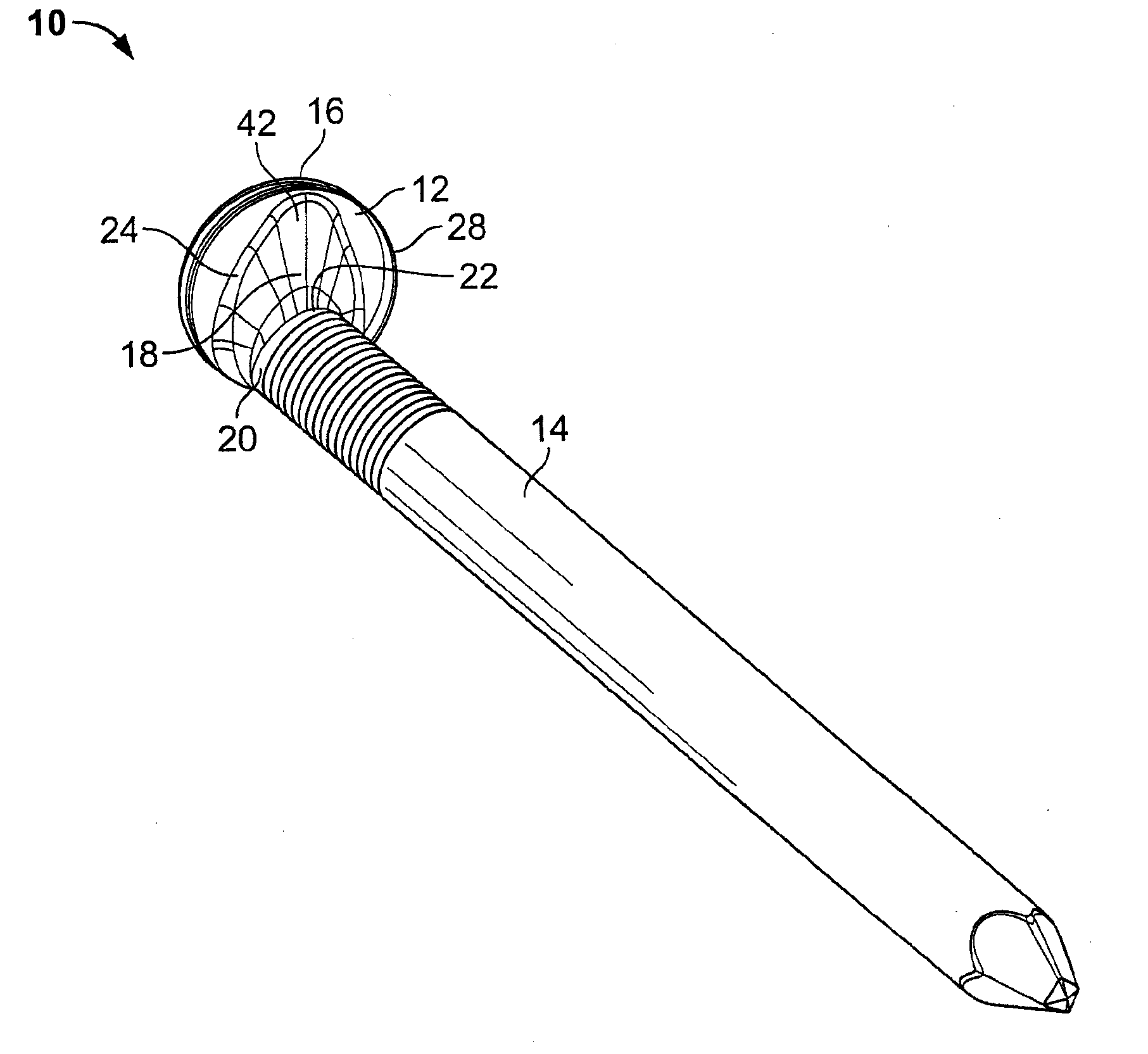
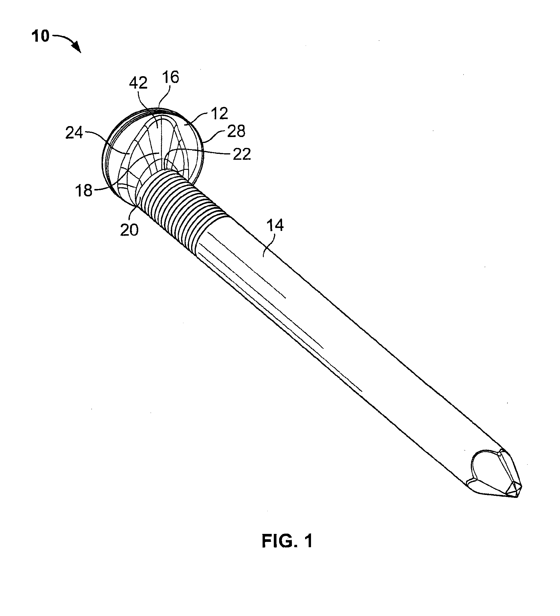
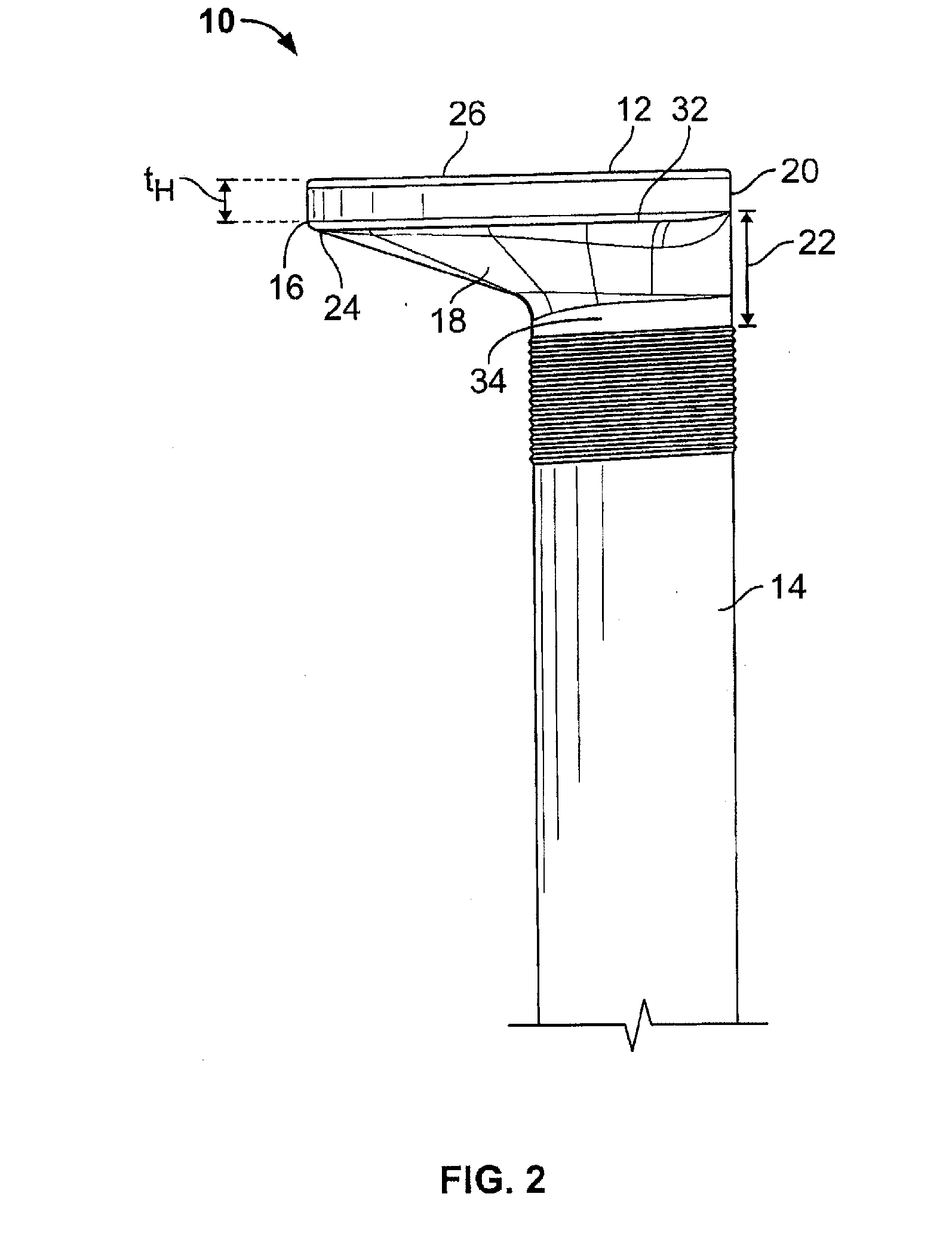
[0033]The present invention pertains particularly to an offset, support-gusseted, nail (hereafter “offset nail”), methods of making the offset nail, and the die used to form the offset nail. The offset nail is formed from a wire of plain or galvanized steel, aluminum, copper, stainless steel, or other metallic or non-metallic material...


PUM


Abstract

A nail having an offset head is configured with a multi-step support gusset formed integrally between an undersurface of the offset head and a superior portion of a shank. The head of the nail is relatively thin, and the shank is positioned radially off center of the head. A first portion of the gusset defines an angle relative to the shank axis and the second portion of the gusset defines an angle relative to the shank axis different from that of the first portion. The support gusset reinforces the junction of the shank with the head, supports the toe of the head, and distributes the force of a load on the head through a longitudinal axis of the shank, preventing the toe from bending or yielding and prevents the shank from yielding to the stresses of the load applied.

Description

CROSS-REFERENCE TO RELATED APPLICATION[0001]This application is a continuation-in-part of and claims the benefit of priority to U.S. patent application Ser. No. 12 / 175,704, filed Jul. 18, 2008, entitled “APPARATUS AND METHOD OF MAKING A HEEL-LESS NAIL”.BACKGROUND OF THE INVENTION[0002]The present invention is directed to a nail. More particularly, the present invention pertains to a radially offset, full or partially round headed nail and a method of making same.[0003]Nails are often used in power driving tools to quickly and efficiently secure objects such as wood. Generally, nails have a head and an elongated shank and are linearly collated in an adhesive strip made of plastic or paper tape or the like, with the shanks oriented in a parallel relationship. The nails are ejected sequentially as the driver blade of the power driving tool strikes each of the heads individually. The nails in the strip are, therefore, spaced apart so that the heads do not interfere with each other durin...

Claims


Application Information

Patent Timeline
Patent Type & Authority Applications(United States)
IPC IPC(8): F16B15/02B21G3/00
CPCB21G3/12F16B15/02Y10S411/923
Inventor ALI, ZAFAR I.BERGSTROM, DONALD E.GABRIEL, WILLIAM L.
Owner ILLINOIS TOOL WORKS INC
Why Eureka
Try Eureka