Roller for Pelleting Mill

a technology of rollers and pellets, which is applied in the direction of dough shaping, application, manufacturing tools, etc., can solve the problems of frequent or continuous lubrication, pellets can become contaminated by lubricant, and rollers would become damaged within a few hours of operation

Inactive Publication Date: 2010-07-22
ALLIS CARL R
View PDF15 Cites 21 Cited by
  • Summary
  • Abstract
  • Description
  • Claims
  • Application Information

AI Technical Summary

Problems solved by technology

A problem with conventional rollers is that they require frequent or continuous lubrication because of their tendency to leak lubrication and the tendency of foreign material to find their way inside the rollers.
Without lubrication replenishment and flushing, rollers would become damaged within a few hours of operation.
Another problem with conventional rollers is that pellets can become contaminated by the lubricant that leaks out.
Yet another disadvantage is the need to periodically monitor and purchase lubricant, which increases the cost of operations.

Method used


Image

  • Roller for Pelleting Mill
  • Roller for Pelleting Mill
  • Roller for Pelleting Mill

Examples


Embodiment Construction

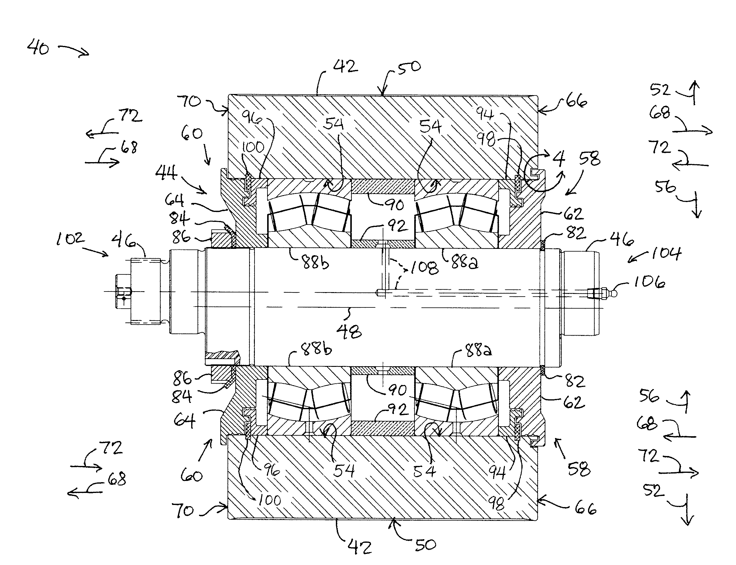
[0021]Referring now in more detail to the exemplary drawings for purposes of illustrating embodiments of the invention, wherein like reference numerals designate corresponding or like elements among the several views, there is shown in FIG. 3 a roller assembly 40 for use with a pellet mill.

[0022]The roller assembly includes a hollow cylinder 42 having a central bore 44 in which other components are located. The hollow cylinder is adapted to rotate about a shaft 46 extending through the central bore 44. The rotational axis of the hollow cylinder is depicted as line 48. The cylinder 42 has a curved, outer surface 50 that is exposed, faces in a radially outward direction 52, and is adapted to push particulate material into extrusion holes of a pellet die of the pellet mill. The cylinder 42 also has a curved, inner surface 54 that faces in a radially inward direction 56, and is adapted to cooperate with components in the central bore 44. The cylinder 42 may be made of steel, stainless s...


PUM

PropertyMeasurementUnit
interior anglesaaaaaaaaaa

Abstract

A pellet mill includes a die carrying material to be extruded into pellets. The die rotates to bring the material toward rollers within the die. The rollers push the material through extrusion holes in the die. The rollers are mounted on and rotate about support shafts that are held stationary within the die. Sealing devices at the ends of the rollers prevent foreign material from interfering with bearings between the rollers and the support shafts. Each of the sealing devices include one or more sealing elements. The sealing elements may include a pair of mating grooves and protrusions.

Description

FIELD OF THE INVENTION[0001]This invention relates generally to pelletizing machinery and, more particularly, a roller assembly for a pelleting mill.BACKGROUND OF THE INVENTION[0002]Pellet mills are used to form a variety of pellet products from various grains or other particulate material. As shown in FIG. 1, a conventional pellet mill 10 includes a die 12 that carries particulate material 14 to be made into pellets 16. As the die rotates about its central axis 17, rollers 18 inside the die rotate about their respective central axes 19 and force the material 14 through extrusion holes 20 in the die. Rotation of the rollers 18 allows for proper and efficient extrusion of the material 14. The extruded material that exits the die may be sheared off by blades 22 located outside the die.[0003]Referring to FIG. 2, the particulate material is fed into one end 24 of the die 12. The die 12 is connected to and rotated by a flange 26 at the end of a quill shaft 28. The quill shaft is tubular ...

Claims


Application Information

Patent Timeline
Patent Type & Authority Applications(United States)
IPC IPC(8): B29C47/00
CPCB30B11/208F16C13/02F16C33/80F16C2320/23B29B9/06
Inventor ALLIS, CARL R.
Owner ALLIS CARL R
Why Eureka
Try Eureka