Implant erecting drill toll, hand-piece, adaptor for the hand-piece, and surgical guide

a technology for erecting drills and implants, which is applied in the field of implant erecting drilling tools, handpieces, handpiece adaptors for handpieces, and surgical guides, can solve the problems of difficulty in achieving proper occlusion between the artificial tooth supported by the implant and the counter tooth, and the drilled hole is dimensionally and morphologically unbalanced with respect to adjacent teeth, so as to achieve accurate drilling and drilling the effect of the desired angl

Inactive Publication Date: 2010-07-22
IMAGNOSIS
View PDF10 Cites 55 Cited by
  • Summary
  • Abstract
  • Description
  • Claims
  • Application Information

AI Technical Summary

Benefits of technology

[0030]According to the inventive aspect of claim 1, the head of the implant handpiece has the round outer peripheral surface concentric with the center axis of the drill bur and having a length greater than the predetermined length as measured axially of the drill bur. Therefore, the drill bur can be slid at a desired angle in a desired direction based on the round peripheral surface of the head by moving the implant handpiece axially of the drill bur along the round peripheral surface of the head. This makes it possible to accurately drill a hole at the desired angle in the desired direction by means of the drill bur.
[0031]The guide hole of the surgical guide for guiding the implant handpiece is not adapted to guide the drill bur as in the prior art, but adapted to guide the head of the implant handpiece. The guiding of the head is a novel idea. For guiding the head but not the drill bur, the guide hole has the arcuate inner peripheral surface to be opposed to the round peripheral surface of the head. Therefore, a drilling operation can be accurately performed by moving the round peripheral surface of the head along the inner peripheral surface axially of the drill bur.
[0032]Thus, the inventive implant implantation drilling tool is based on a novel idea of guiding the head of the implant handpiece through the hole of the surgical guide. Therefore, the head of the implant handpiece has a unique outer shape as described in claim 1. Further, the guide hole of the surgical guide is configured so as to guide the head of the unique shape.
[0033]According to the inventive aspect of claim 2, the neck connected to the head of the implant handpiece is smaller in size than the head. Since the distal end of the neck is smaller in size than the head, the head can be rotated in a desired direction within the guide hole of the surgical guide.
[0034]Particularly, where the guide hole of the surgical guide has the opening having an opening angle less than 180 degrees as described in claim 3, the distal end of the neck can pass through the opening, and the head is rotatable about the axis thereof and axially slidable without offset from the inner peripheral surface.
[0035]Where an implant implantation hole is drilled into a patient's jawbone by means of the drill bur, it is a common practice to perform the drilling operation while supplying cooling water in order to prevent the jawbone from being adversely affected by frictional heat generated during the drilling operation. Since the water flow channel through which the cooling water flows back is provided in one of the outer peripheral surface of the head and the inner peripheral surface of the guide hole according to the inventive aspect of claim 4, it is possible to ensure proper flow of the cooling water (supply of the cooling water and drain of the supplied cooling water) while properly guiding the head of the implant handpiece through the hole of the surgical guide.

Problems solved by technology

Since it is difficult to adjust the rotation speed of the turbine and supply a stable torque, it is a current practice to use a handpiece of the electric motor type for the implantation.
If the implant is implanted at an improper position, it is difficult to achieve proper occlusion between an artificial tooth supported by the implant and the counter tooth.
Further, the artificial tooth for the prosthesis is dimensionally, positionally and morphologically unbalanced with respect to adjacent teeth.
Indefinite positioning for the drilling, repetition of the drilling, modification of the drilled hole and wobbling during the drilling cause the drilled hole to have a greater size than the implant to be implanted, resulting in loose fitting of the implant in the bone.
This makes it impossible to provide sufficient initial fixing, so that the implantation per se will be failed.
That is, the guide indeed serves as a reference, but fails to accurately guide the drill but at the position in the direction determined through the diagnosis.

Method used


Image

  • Implant erecting drill toll, hand-piece, adaptor for the hand-piece, and surgical guide
  • Implant erecting drill toll, hand-piece, adaptor for the hand-piece, and surgical guide
  • Implant erecting drill toll, hand-piece, adaptor for the hand-piece, and surgical guide

Examples


Embodiment Construction

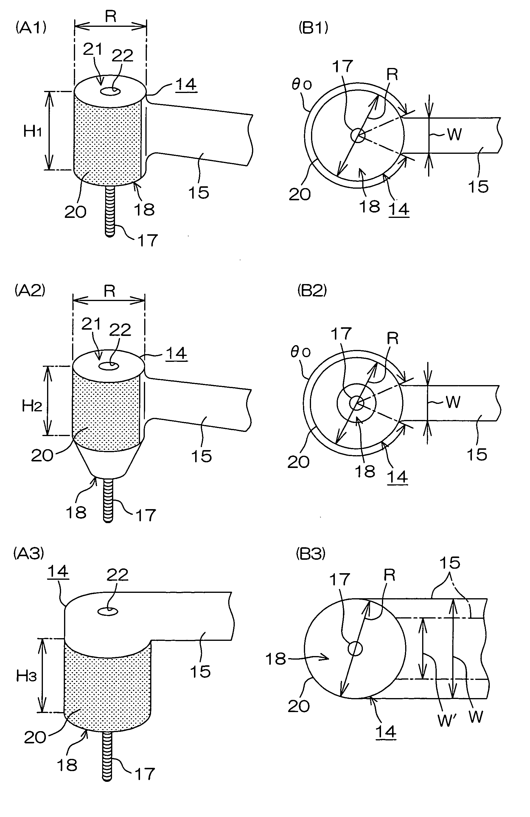
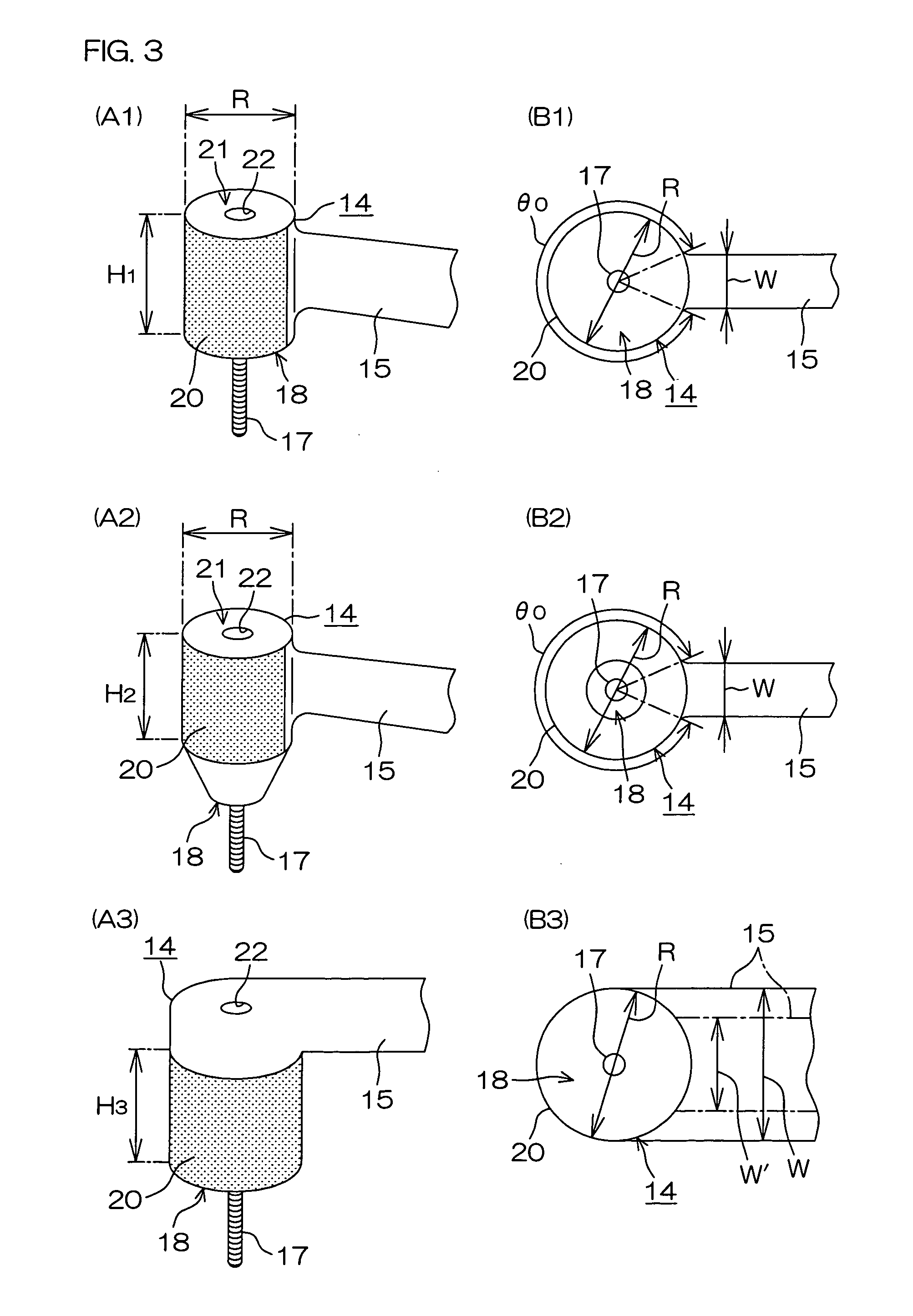
[0083]Embodiments of the present invention will hereinafter be described more specifically with reference to the attached drawings.

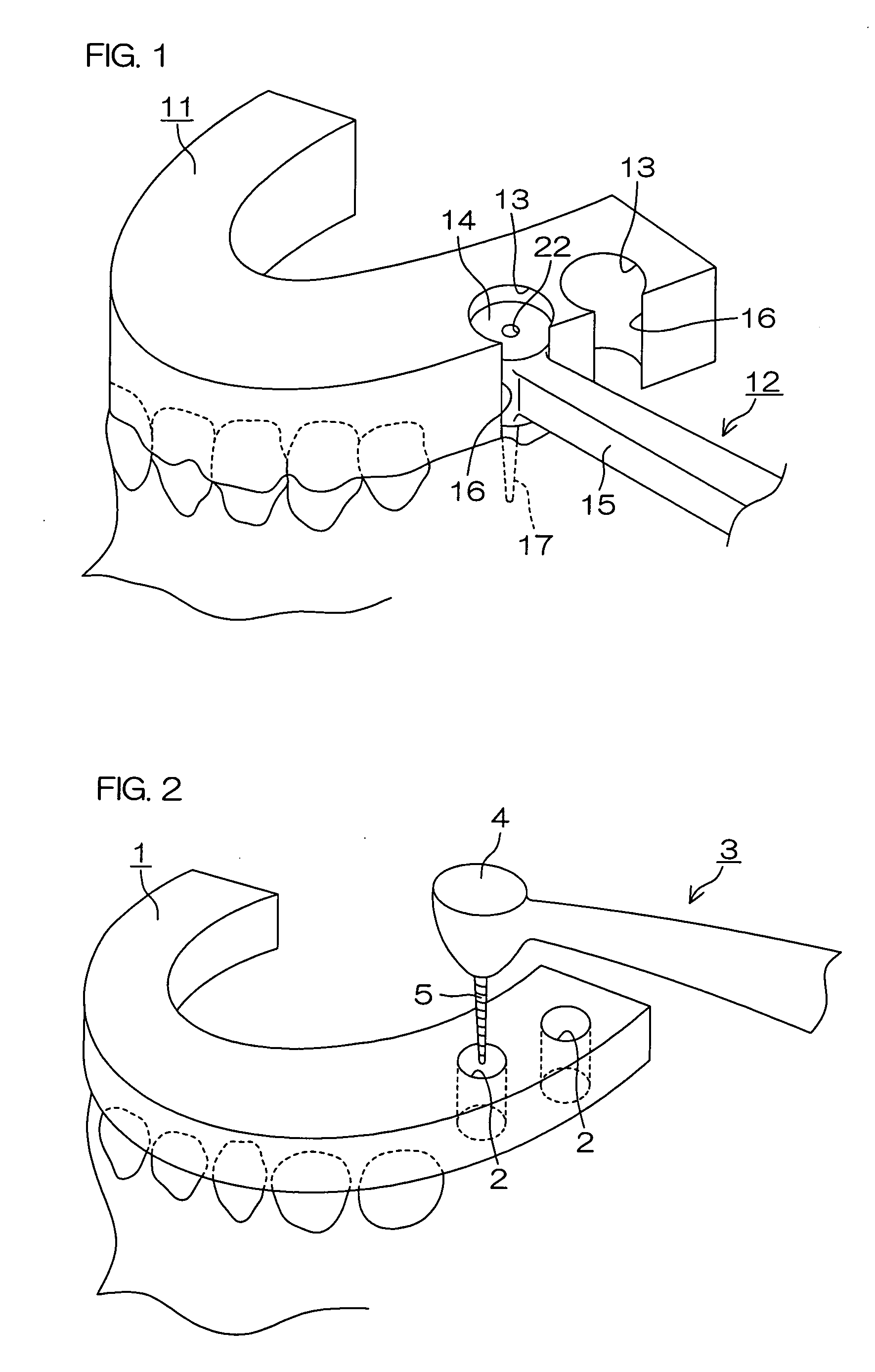
[0084]FIG. 1 is a schematic diagram showing how to drill an implant implantation hole in a patient's jawbone with the use of an implant implantation drilling tool according to one embodiment of the present invention. FIG. 2 is a schematic diagram showing how to drill an implant implantation hole in a patient's jawbone with the use of a dental handpiece and a surgical guide according to the prior art.

[0085]First, a method of forming the implant implantation hole according to the prior art will be described with reference to FIG. 2.

[0086]The conventionally used surgical guide 1 has a guide hole 2 for guiding a drill bur 5. With the surgical guide 1 fitted in the patient's oral cavity, the guide hole 2 formed in the surgical guide 1 defines a position and an angle for guiding the drill bur 5 when a drilling operation is performed at an implant implantation ...


PUM


Abstract

An inventive implant handpiece (12) includes a head (14) having a round outer peripheral surface (20) which is concentric with a center axis of a drill bur (17) and has a predetermined length (H1 to H3) as measured axially of the drill bur (17). A surgical guide (11) has a guide hole (13) having a round inner peripheral surface to be opposed to the round peripheral surface (20) of the head (14). Since a drilling operation is performed with the head (14) fitted in the guide hole (13), the head (14) can be reliably uniquely guided to form an implant implantation hole as desired. Thus, the present invention provides an implant handpiece capable of accurately drilling a hole for formation of an implant implantation hole, and a surgical guide capable of guiding this handpiece.

Description

TECHNICAL FIELD[0001]The present invention relates to an implant implantation drilling tool, a handpiece, a handpiece adaptor, and a surgical guide.BACKGROUND ART[0002]An implant handpiece related to the present invention will be first described.[0003]In general, dental cutting tools are classified into a turbine type adapted to rotate a drill bur at a high speed by compressed air and a handpiece type adapted to rotate a drill bur by an electric motor. The turbine (air turbine) type is mainly used for cutting a tooth. When a hole is drilled into a jawbone for implantation of an implant, on the other hand, it is necessary to rotate a drill at a lower speed with a stable torque for prevention of heat generation. Since it is difficult to adjust the rotation speed of the turbine and supply a stable torque, it is a current practice to use a handpiece of the electric motor type for the implantation.[0004]The implant handpiece related to the present invention is of the electric motor type....

Claims


Application Information

Patent Timeline
Patent Type & Authority Applications(United States)
IPC IPC(8): A61B17/00A61B17/56
CPCA61C1/084A61C1/12A61C1/10
Inventor KIM, HAN-JOON
Owner IMAGNOSIS
Why Eureka
Try Eureka