Heat exchange unit

a heat exchange unit and heat exchange resin technology, applied in the direction of lighting and heating apparatus, machine operation mode, etc., can solve the problems of small cracks and fractures in the insulating resin layer, drawbacks recur, etc., to improve the adhesion, prevent cracks and fractures, and optimize the surface roughness of the heat exchanger

Inactive Publication Date: 2010-07-29
YAMAHA CORP
View PDF12 Cites 12 Cited by
  • Summary
  • Abstract
  • Description
  • Claims
  • Application Information

AI Technical Summary

Benefits of technology

[0016]Due to the optimized surface roughness of the heat exchanger, it is possible to prevent cracks and fractures from being formed in the insulating layer, it is possible to improve the adhesion between the heat exchanger and the insulating layer, and it is possible to reduce the thermal resistance and to thereby improve the heat-absorption / dissipation performance and the reliability in the heat exchange unit.

Problems solved by technology

This is because the dispersion of “hard” fillers leads to the formation of small cracks and fractures in the insulating resin layer due to pressurization during thermocompression bonding.
This drawback recurs even when the insulating resin layer is hardened by applying a varnish resin.

Method used


Image

  • Heat exchange unit
  • Heat exchange unit
  • Heat exchange unit

Examples


first embodiment

1. First Embodiment

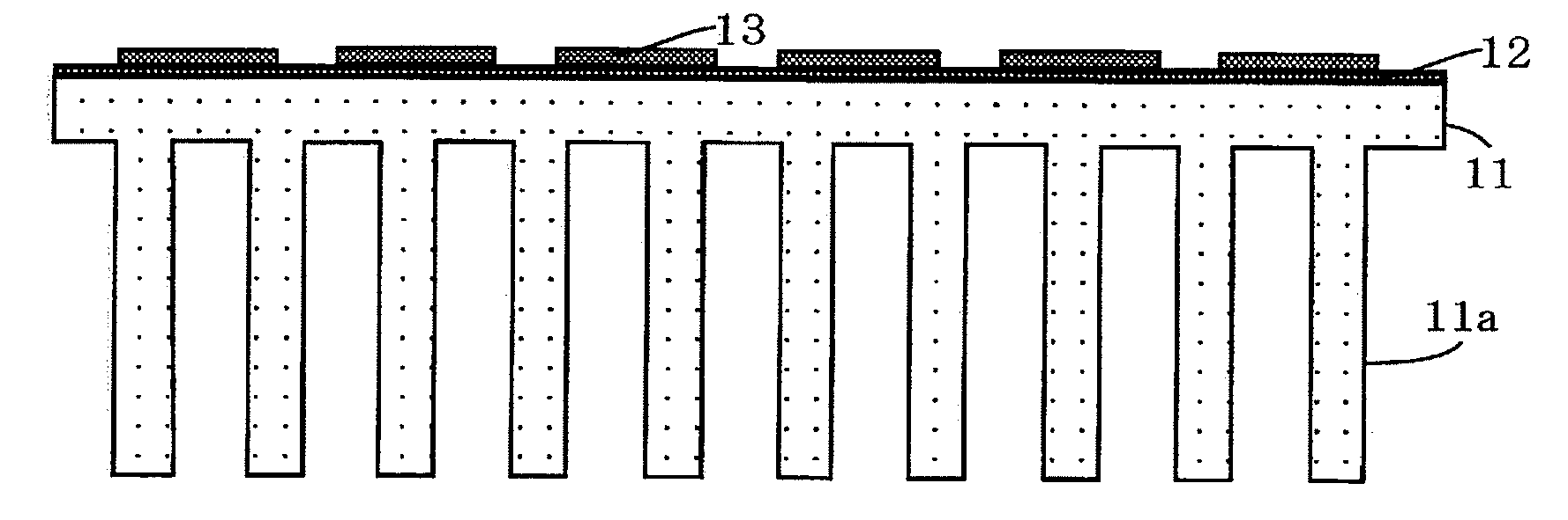
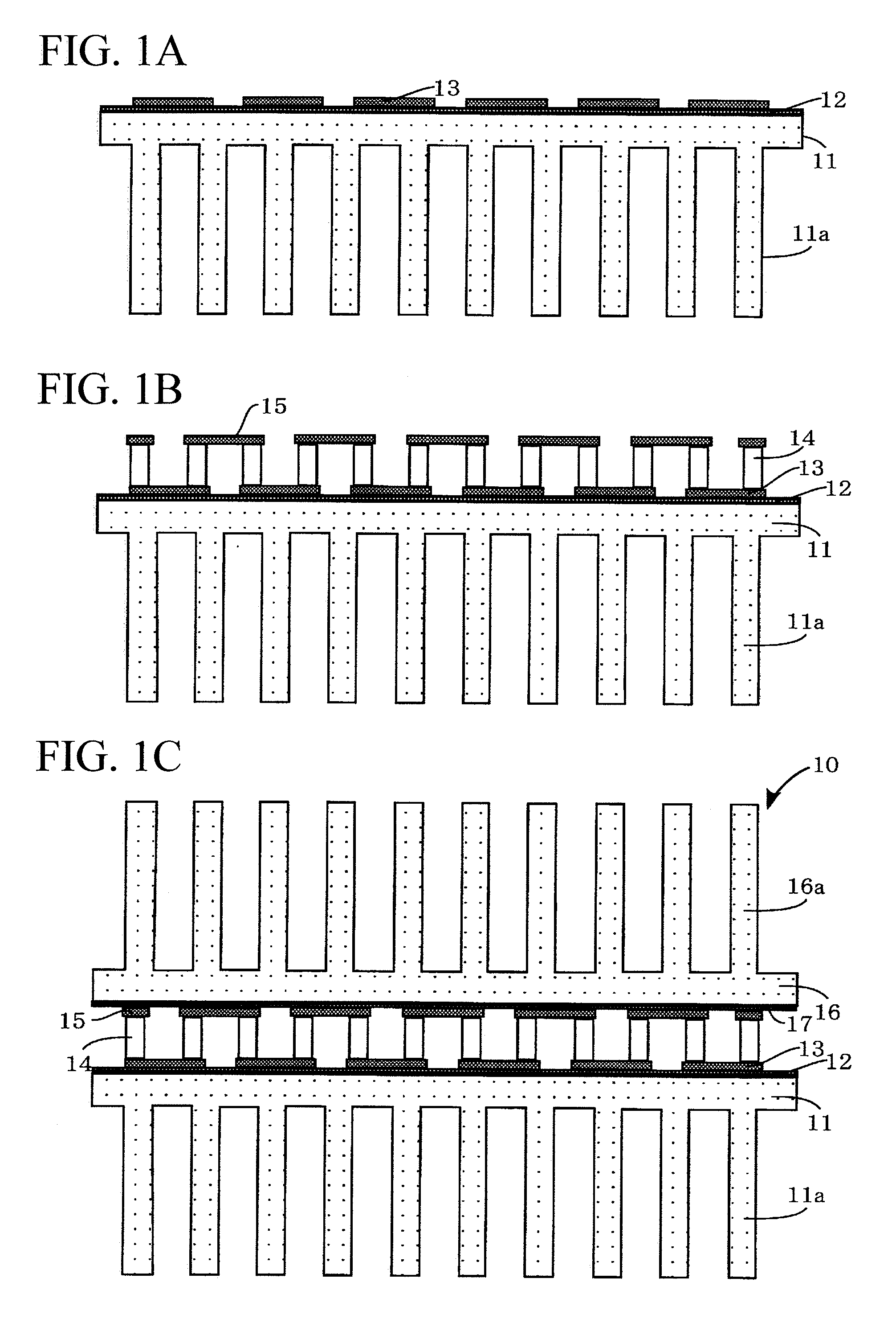
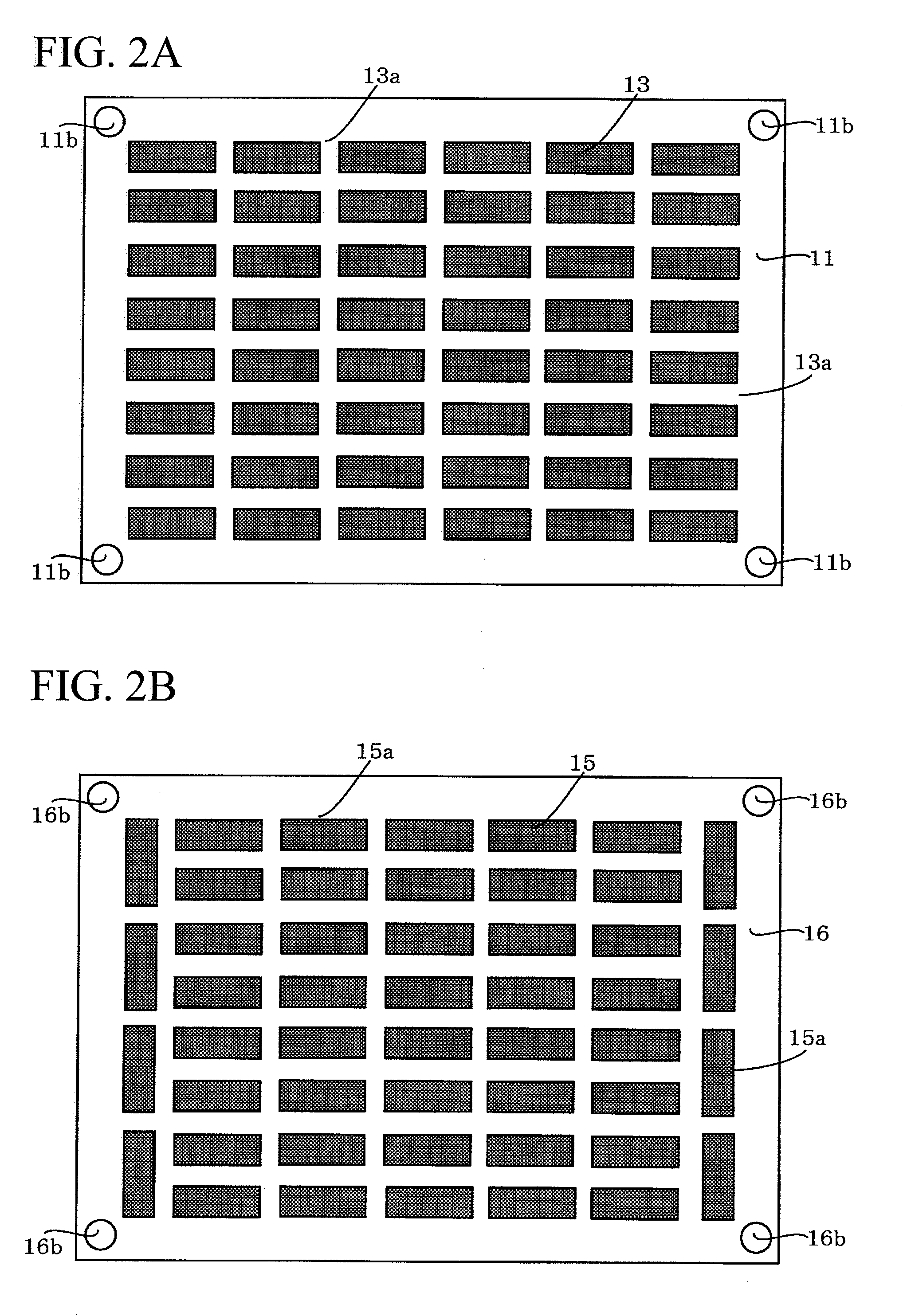
[0043]A heat exchange unit 10 according to a first embodiment of the present invention will be described with reference to FIGS. 1A to 1C. As shown in FIG. 1C, the heat exchange unit 10 is constituted of a first heat exchanger (serving as a heat-dissipation or heat-absorption air-cooled heatsink) 11, an insulating layer 12 formed on the surface of the first heat exchanger 11, a lower electrode (serving as a heat-dissipation or heat-absorption electrode) 13 disposed on the insulating layer 12, a plurality of thermoelectric elements 14 bonded onto the lower electrode 13, an upper electrode (serving as a heat-dissipation or heat-absorption electrode) 15 bonded onto the thermoelectric elements 14, a second heat exchanger (serving as a heat-dissipation or heat-absorption air-cooled heatsink) 16, and an insulating layer 17 formed on the surface of the second heat exchanger 16. A pair of terminals connected to a pair of leads (both not shown) is formed on one end of the ...

second embodiment

2. Second Embodiment

[0084]The first embodiment is directed to the heat exchange unit 10 constituted of the first heat exchanger 11 and the second heat exchanger 16 each serving as air-cooled heatsinks, which is not a restriction; hence, it is possible to employ a water-cooled heatsink. A second embodiment is designed to use water-cooled heatsinks as first and second heat exchangers.

[0085]A heat exchange unit 20 according to a second embodiment of the present invention will be described with reference to FIGS. 6A to 6C. As shown in FIG. 6C, the heat exchange unit 20 is constituted of a first heat exchanger (serving as a heat-dissipation or heat-absorption water-cooled heatsink) 21, an insulating layer 22 formed on the surface of the first heat exchanger 21, a lower electrode (serving as a heat-dissipation or heat-absorption electrode) 23 disposed on the insulating layer 22, a plurality of thermoelectric elements 24 bonded onto the lower electrode 23, an upper electrode (serving as a ...

third embodiment

3. Third Embodiment

[0116]The heat exchange unit 10 of the first embodiment and the heat exchange unit 20 of the second embodiment are designed such that the electrodes 13, 15, 23, and 25 are uniformly formed on the surfaces of the heat exchangers 11, 16, 21, and 26; but when prescribed areas on the surfaces of the heat exchangers do not allow for the uniform alignment of the electrodes thereon, it is possible to align the electrodes so as to be kept out of the prescribed areas on the surfaces of the heat exchangers. A third embodiment of the present invention is designed based on this concept.

[0117]A heat exchange unit 30 according to the third embodiment of the present invention will be described with reference to FIGS. 10A to 10C. As shown in FIG. 10C, the heat exchange unit 30 is constituted of a first heat exchanger (serving as a heat-dissipation or heat-absorption water-cooled heatsink) 31, insulating layers 32a and 32b formed on the surface and the backside of the first heat e...


PUM

PropertyMeasurementUnit
surface roughnessaaaaaaaaaa
surface roughness Raaaaaaaaaaa

Abstract

A heat exchange unit is constituted of a thermoelectric module and a heat exchanger. The thermoelectric module includes an upper electrode, a lower electrode, and a plurality of thermoelectric elements interposed between the upper electrode and the lower electrode, wherein the heat exchanger composed of aluminum or aluminum alloy having high thermal conductivity is attached to the upper electrode and/or the lower electrode via an insulating layer. The surface roughness of the heat exchanger adjoined to the insulating layer is controlled to be less than 4.7 μm and greater than 0.1 μm. This prevents cracks and fractures from being formed in the insulating layer, which is thus improved in adhesion with the heat exchanger. Thus, it is possible to demonstrate high heat-absorption/dissipation performance and high reliability in the heat exchange unit due to a reduced thermal resistance between the thermoelectric module and the heat exchanger.

Description

BACKGROUND OF THE INVENTION[0001]1. Field of the Invention[0002]The present invention relates to heat exchange units including thermoelectric modules in which thermoelectric elements of different types are alternately aligned and electrically connected in series between heat-absorption electrodes and heat-dissipation electrodes.[0003]The present application claims priority on Japanese Patent Application No. 2009-18498, the content of which is incorporated herein by reference.[0004]2. Description of the Related Art[0005]Conventionally, thermoelectric modules have been developed and designed such that thermoelectric elements composed of P-type semiconductors and N-type semiconductors are alternately aligned and connected in series and are held between heat-absorption electrodes and heat-dissipation electrodes via metals such as soldering metals. Various documents disclose heat exchange units in which heat exchangers join to heat-absorption electrodes or heat-dissipation electrodes of ...

Claims


Application Information

Patent Timeline
Patent Type & Authority Applications(United States)
IPC IPC(8): F25B21/02
CPCH01L23/38H01L23/427H01L35/30H01L2924/0002H01L2924/00H10N10/13
Inventor HORIO, YUMA
Owner YAMAHA CORP
Why Eureka
Try Eureka