

Electric power cable
- Summary
- Abstract
- Description
- Claims
- Application Information
AI Technical Summary
Benefits of technology
Problems solved by technology
Method used
Image

Examples
Embodiment Construction
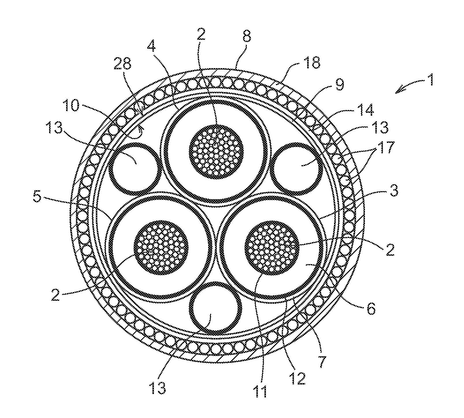
[0036]FIG. 1 shows a cross section of an electric power sea cable 1, comprising one single-conductor cable core 3 comprising an electrical conductor 2, and an electric insulation 6 of polymer surrounding the conductor 2. An inner conducting layer 11 is arranged between the conductor 2 and the electric insulation 6, and an outer conducting layer 12 is arranged outside and in contact with the insulation 6. A protective sheath 7 surrounds the outer conducting layer 12 and acts as a water barrier that prevents water intrusion into the electric insulation 6, and one outer layer 8 is arranged around the protective sheath 7. The outer layer 8 may comprises several layers such as armoring (not shown) and an outer jacket (not shown) to protect the cable core 3 mechanically. A friction reducing layer 9 is arranged inside of the outer layer 8 and at least partly in contact with the protective sheath 7. The friction reducing layer 9 is made of polypropylene, and has a thickness in the interval ...
PUM
 Abstract
Description
Claims
Application Information