Rigid tipped riblets
a technology of rigid ribs and riblets, applied in the direction of boundary layer controls, air flow influencers, synthetic resin layered products, etc., can solve the problems of reducing the durability of the surface, reducing the service life of the structure, and existing solutions with polymeric tips that may easily deform hundreds of percent with fingernail pressure, etc., to achieve the effect of greater flexibility
- Summary
- Abstract
- Description
- Claims
- Application Information
AI Technical Summary
Benefits of technology
Problems solved by technology
Method used
Image
Examples
first embodiment
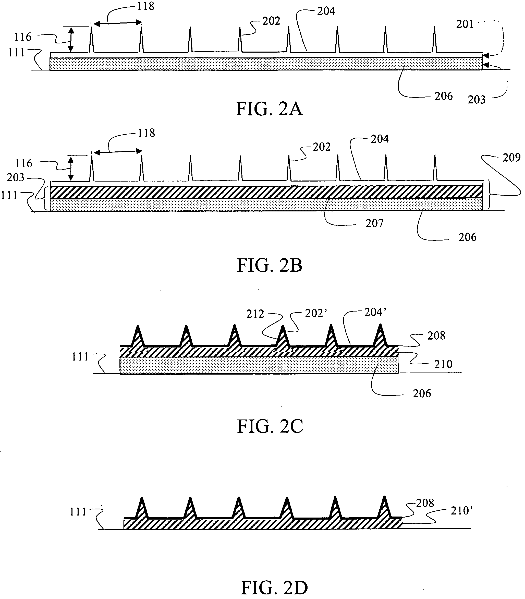
[0039]A first embodiment for rigid tipped riblets is shown in FIG. 2A as a multilayer construction. Individual tips 202 of the riblets protrude from a surface layer 204 to provide a first layer 201 of the multilayer construction. The protruding riblets and continuous surface layer are formed by casting or deposition, as will be described in greater detail subsequently, of the rigid material desired for providing a first characteristic of durability. In an exemplary embodiment, nickel is employed. For the embodiment shown in FIG. 2A a second layer 203 created by an adhesive layer 206 is deposited on a bottom 204a of the surface layer 204. Exemplary adhesives for use in various embodiment may include, without limitation, acrylic pressure sensitive adhesive, sylilated polyurethane pressure sensitive adhesive; thermoplastic adhesive; heat-reactive adhesive or epoxy adhesive. In alternative embodiments, a supporting polymer layer 207 engages the surface layer 204 intermediate the surface...
third embodiment
[0046]FIG. 4 demonstrates a third embodiment for the rigid tipped riblets 112 in FIG. 1 which takes advantage of the structural capability provided by the material from which the riblets 112 are formed to allow a sharper profile of tips 402. For the embodiment shown in each of the tips 402 extends from a base 406 supported in an elastomer layer 404. As with the embodiment described with respect to FIG. 3 the base 406 of each tip 402 is surrounded by the elastomer to structurally retain the base 406 within the elastomer layer 404. In alternative embodiments, the extended bottom surface 408 of the base 406 may be adhered to the surface 404a of the elastomer layer 404. The embodiment of FIG. 4 also employs riblet tips 402 separated perpendicular to the flow direction 114 as in the embodiment of FIG. 3. However, in alternative embodiments a continuous surface layer 204 from which the tips 202 extend as disclosed for the embodiment described with respect to FIG. 2A may be employed.
[0047]...
PUM
| Property | Measurement | Unit |
|---|---|---|
| Elastomeric | aaaaa | aaaaa |
| Adhesivity | aaaaa | aaaaa |
| Metallic bond | aaaaa | aaaaa |
Abstract
Description
Claims
Application Information
 - R&D
- Intellectual Property
- Life Sciences
- Materials
- Tech Scout
- Unparalleled Data Quality
- Higher Quality Content
- 60% Fewer Hallucinations
Browse by: Latest US Patents, China's latest patents, Technical Efficacy Thesaurus, Application Domain, Technology Topic, Popular Technical Reports.
© 2025 PatSnap. All rights reserved.Legal|Privacy policy|Modern Slavery Act Transparency Statement|Sitemap|About US| Contact US: help@patsnap.com


