Omni-directional wheel

a technology of omni-directional wheels and wheels, applied in the direction of loading/unloading vehicle arrangment, transportation items, transportation and packaging, etc., can solve the problems of limiting the load carrying capacity of the wheel, increasing the friction and wear of the omni-directional wheel, and increasing the friction and wear of the wheel. , to achieve the effect of reducing the load, reducing vibration, and increasing the load

Active Publication Date: 2010-07-29
FOSTER-MILLER
View PDF23 Cites 70 Cited by
  • Summary
  • Abstract
  • Description
  • Claims
  • Application Information

AI Technical Summary

Benefits of technology

[0023]Use of a suspension system is desirable, especially in the case of a 4-wheel omni-vehicle since this equalizes the load on the wheels and avoids rocking on diagonal opposed wheels. The invention features a particularly advantageous suspension wherein each wheel is allowed to move vertically with respect to the vehicle chassis. This keeps the wheel axes approximately parallel to the ground which minimizes vibration due to ride height variation.
[0024]The suspension can be actively controlled to raise and lower the chassis. This provides the ability to drive under a payload (supported on legs). The payload can then be lifted, transported and set back down. The active suspension can also be used to reduce the load on one pair of diagonally opposed omni-wheels, while increasing the load on the other pair of diagonally opposed wheels. This allows the vehicle to more easily climb a step or drive over an obstacle such as a cable or chain. The active suspension can also control the pitch and roll of the chassis relative to the ground or other driving surface.

Problems solved by technology

There are several problems associated with typical omni-directional wheels of the prior art.
The resultant scrubbing causes increased rolling friction and wear.
Small tapered rollers also limit the load carrying capacity of the wheel.
In some implementations, however, a larger wheel cannot be accommodated.
Prior art omni-directional wheels also have a limited capacity to traverse obstacles when the wheel travels sideways.

Method used


Image

  • Omni-directional wheel
  • Omni-directional wheel
  • Omni-directional wheel

Examples


Embodiment Construction

[0045]Aside from the preferred embodiment or embodiments disclosed below, this invention is capable of other embodiments and of being practiced or being carried out in various ways. Thus, it is to be understood that the invention is not limited in its application to the details of construction and the arrangements of components set forth in the following description or illustrated in the drawings. If only one embodiment is described herein, the claims hereof are not to be limited to that embodiment. Moreover, the claims hereof are not to be read restrictively unless there is clear and convincing evidence manifesting a certain exclusion, restriction, or disclaimer.

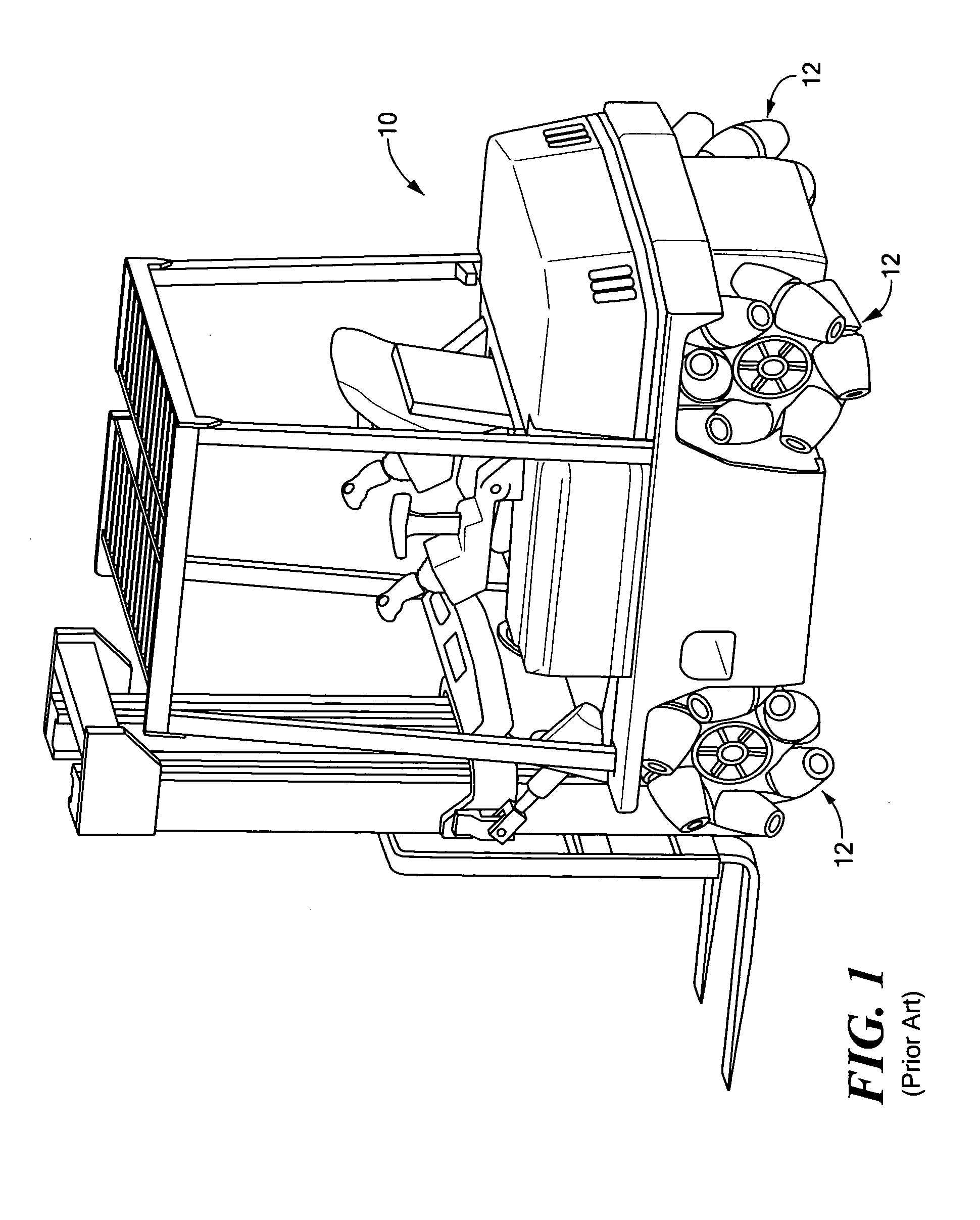
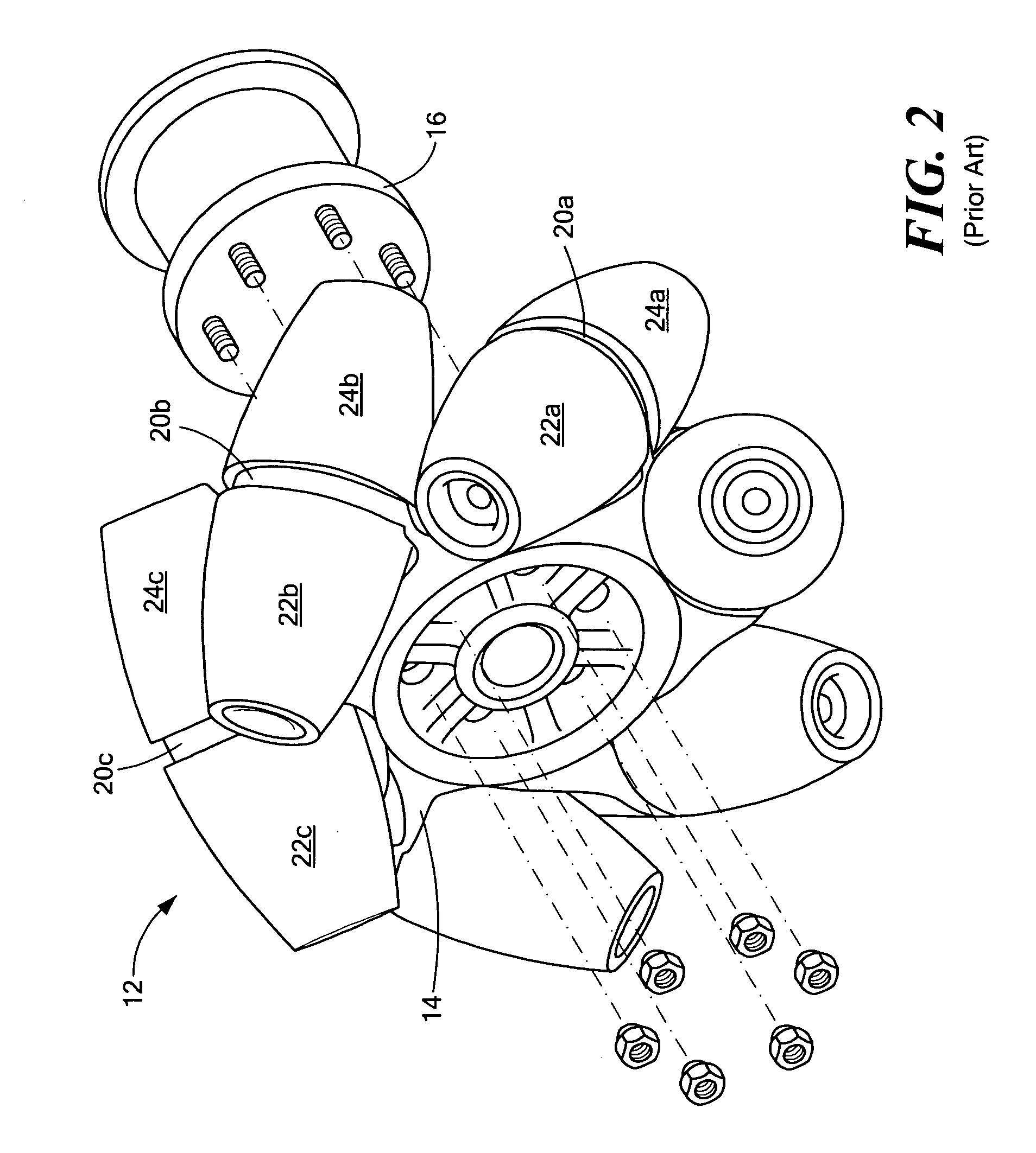
[0046]FIG. 1 shows forklift 10 with omni-directional wheels 12 in accordance with U.S. Pat. No. 6,547,340. Each omni-directional wheel 12, FIG. 2 includes hub 14 mounted to axle 16. Hub 14 has seven mounting tabs, of which only 20a-20c are visible. Each mounting tab supports a pair of tapered rollers. For example, tab 20a s...


PUM

PropertyMeasurementUnit
roller angleaaaaaaaaaa

Abstract

An omni-directional wheel includes a hub rotatable about a wheel axis and a first row of angled rollers about the hub each rotatably supported by the hub. There is at least a second row of angled rollers about the hub each also rotatably supported by the hub. The rollers of the second row are axially offset along the wheel axis from the first row, and rotationally offset from the first row about the wheel axis, and not coaxial with the rollers of the first row.

Description

GOVERNMENT RIGHTS[0001]Certain aspects of this invention were made with U.S. Government support under Contract No. N68335-03-D-0101 by the US Navy. The Government may have certain rights in the subject invention.FIELD OF THE INVENTION[0002]The subject invention relates to omni-directional wheels and vehicles.BACKGROUND OF THE INVENTION[0003]A wheel that is capable of sideways movement is shown in U.S. Pat. Nos. 3,876,255 and 6,547,340 both incorporated herein by this reference. Other prior art regarding “omni-directional” wheels includes U.S. Pat. Nos. 6,857,707; 4,223,753; 6,340,065; 4,907,692; 6,394,203; 6,857,707; 4,715,460; 5,374,879; and 3,465,843. These references are also incorporated herein by this reference.[0004]As shown in U.S. Pat. No. 6,547,340, a typical omni-directional wheel includes a hub rotatably mounted to an axle. A number of rollers are mounted to the hub via mounting brackets and the rollers are set at different angles so that as the hub rotates, each roller, ...

Claims


Application Information

Patent Timeline
Patent Type & Authority Applications(United States)
IPC IPC(8): B60G17/00B60B19/12
CPCB60B19/003B60B19/125B60B2310/202B60B2310/228B60B2310/305B66F9/07577B60B2360/324B60B2900/1212B60B2900/131B60B2900/321B60B2900/351B60B2360/104
Inventor POTTER, STEVEN D.
Owner FOSTER-MILLER
Why Eureka
Try Eureka