Magnetic Induction Devices And Methods For Producing Them

a technology of induction device and magnetic field, which is applied in the direction of photomechanical apparatus, magnetic bodies, instruments, etc., can solve the problems of limiting the applicability of such mids for various applications, thin layers, and often too small mids for many applications

Inactive Publication Date: 2010-07-29
ADVANCED MAGNETIC SOLUTIONS
View PDF51 Cites 134 Cited by
  • Summary
  • Abstract
  • Description
  • Claims
  • Application Information

AI Technical Summary

Benefits of technology

[0029]The present invention, in certain embodiments thereof, seeks to provide im

Problems solved by technology

The layers are typically thin and the resultant MIDs are usually too small for many applications.
Additionally, MIDs produced by IC fabrication technologies typically have air cores which limit applicability of suc

Method used


Image

  • Magnetic Induction Devices And Methods For Producing Them
  • Magnetic Induction Devices And Methods For Producing Them
  • Magnetic Induction Devices And Methods For Producing Them

Examples


Embodiment Construction

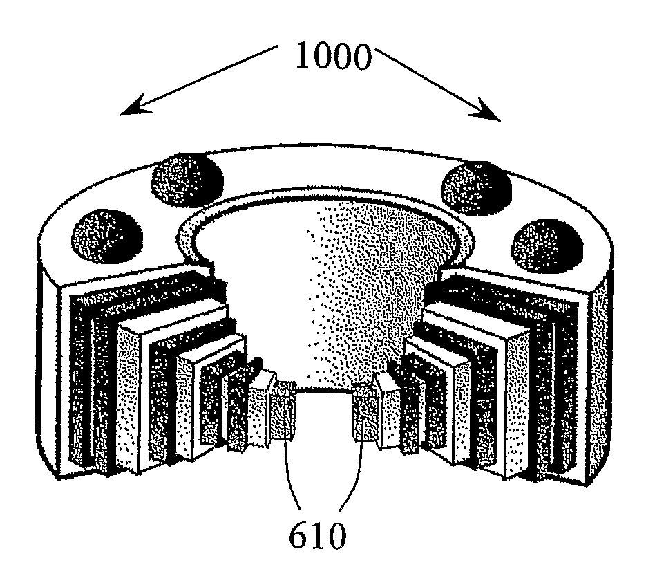
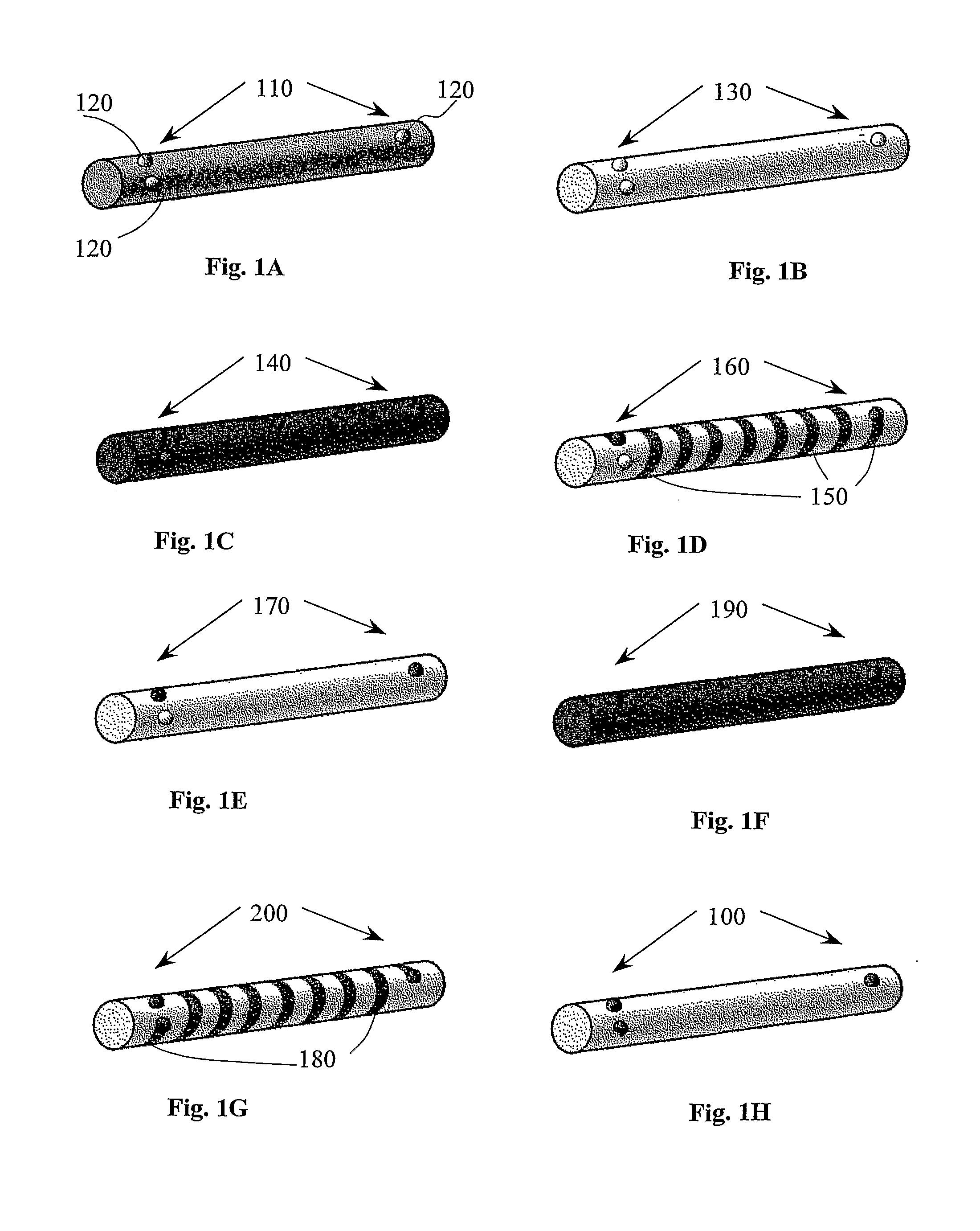
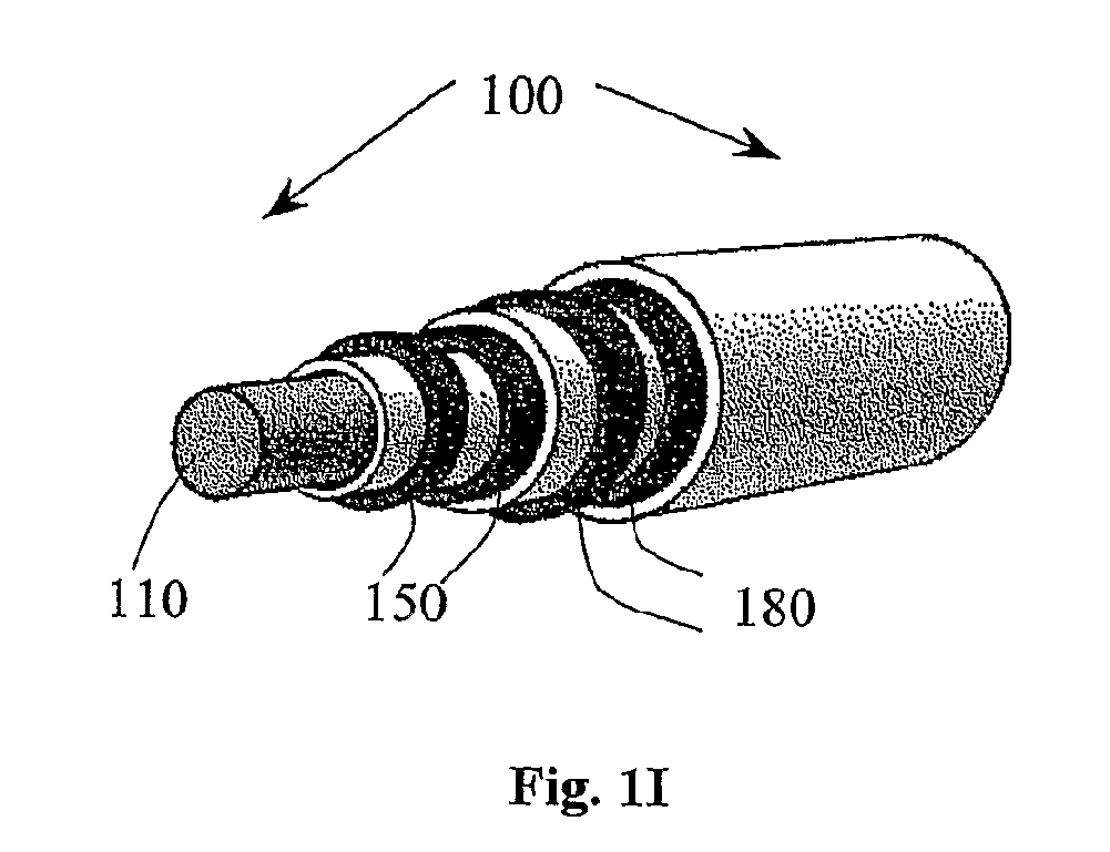
[0089]Reference is now made to FIGS. 1A-1H, which together constitute a simplified pictorial illustration of a magnetic induction device (MID) 100 comprising a cylindrical inductor in various production stages in accordance with an embodiment of the present invention, and to FIG. 1I which is a simplified, un-scaled perspective view of the MID 100 with layer cuts showing various layers around MID core.

[0090]FIG. 1A depicts a cylindrical core 110 which is used as a basis for producing the MID 100. The core 110 may comprise at least one of the following: a magnetic core; a core comprising at least one insulating material; and an air core comprising a cover for supporting at least one winding. It is appreciated that the cover of the air core may, by way of a non-limiting example, be disposable, so that the cover may, for example, be taken out or consumed by a chemical process after the at least one winding is produced.

[0091]The core 110 may have protrusions / pins 120 which may be used as...


PUM

PropertyMeasurementUnit
Timeaaaaaaaaaa
Electrical conductivityaaaaaaaaaa
Surface areaaaaaaaaaaa

Abstract

A magnetic induction device (MID) is disclosed. The MID includes a core, and at least one first winding including at least one conductive strip deposited on the core and including at least two turns which are substantially simultaneously shaped. Related apparatus and methods are also disclosed.

Description

CROSS-REFERENCE TO RELATED APPLICATIONS[0001]The present application claims priority from U.S. Provisional Patent Application Ser. No. 60 / 943,313, filed 12 Jun. 2007, the disclosure of which is hereby incorporated herein by reference.FIELD OF THE INVENTION[0002]The present invention generally relates to magnetic induction devices and to methods for producing magnetic induction devices.BACKGROUND OF THE INVENTION[0003]Magnetic induction devices (MIDs), such as transformers, inductors, loop antennas, Baluns (Balun—Balanced-Unbalanced), etc., are used in many applications, such as communication network applications, power circuit applications, test equipment, and radio-frequency (RF) applications.[0004]In addition to traditional techniques of wire winding, there is a continuous search for new technologies that may eliminate the need for actual winding of wires. Some new techniques use integrated circuit (IC) fabrication technologies or printed circuit board (PCB) fabrication technologi...

Claims


Application Information

Patent Timeline
IPC IPC(8): H01F27/28H01F41/12G03F7/20
CPCH01F17/0033Y10T29/4902H01F41/041H01F27/2895
Inventor SHPIRO, ZEEV
Owner ADVANCED MAGNETIC SOLUTIONS
Why Eureka
Try Eureka