Image sensor and image-capturing device

a technology of image sensor and image, which is applied in the direction of camera focusing arrangement, printer, instruments, etc., can solve the problems of inability to focus detection, dark image, and saturation of outputs of focus detection pixels

Active Publication Date: 2010-07-29
MAXELL HLDG LTD
View PDF8 Cites 64 Cited by
  • Summary
  • Abstract
  • Description
  • Claims
  • Application Information

AI Technical Summary

Benefits of technology

[0016]According to the 10th aspect of the present invention, in the image sensor according to the 3rd aspect, it is preferred that first conversion characteristics with which the focus detection photoelectric conversion unit converts the focus detection light flux having been received thereat to the focus detection signal, are different from second conversion characteristics with which the image-capturing photoelectric conversion unit converts the partial light flux having been received thereat to the image signal; and the reduction unit ensures that the signal level of the focus detection signals output from the plurality of focus detection pixels under a given light receiving condition never exceeds the signal level of the image signals output from the plurality of image-capturing pixels under the given light receiving condition by varying the first conversion characteristics and the second conversion characteristics.
[0017]According to the 11th aspect of the present invention, in the image sensor according to the 10th aspect, it is preferred that the plurality of image-capturing pixels and the plurality of focus detection pixels each includes an output unit; the output unit included in each of the plurality of image-capturing pixels amplifies an electrical signal obtained through photoelectric conversion of the partial light flux executed at the image-capturing photoelectric conversion unit and outputs the amplified electrical signal as the image signal; the output unit included in each of the plurality of focus detection pixels amplifies an electrical signal obtained through photoelectric conversion of the focus detection light flux executed at the focus detection photoelectric conversion unit and outputs the amplified electrical signal as the focus detection signal; and the reduction unit ensures that the signal level of the focus detection signals output from the plurality of focus detection pixels under a given light receiving condition never exceeds the signal level of the image signals output from the plurality of image-capturing pixels under the given light receiving condition by setting a lower amplification factor at the output unit included in each of the plurality of focus detection pixels relative to an amplification factor set at the output unit included in each of the plurality of image-capturing pixels.

Problems solved by technology

However, at the image-capturing device described above, equipped with the image-capturing pixels and the focus detection pixels assuming structures different from each other, the outputs from the focus detection pixels may become saturated even if the outputs from the image-capturing pixels remain unsaturated over a given exposure period and, under such circumstances, focus detection may not be possible.
For instance, while the exposure period may be shortened in order to ensure that the outputs from the focus detection pixels are not saturated during focus detection executed concurrently as the outputs from the image-capturing pixels are brought up on display at an electronic viewfinder, the shortened exposure period often results in a dark image due to insufficient image-capturing pixel output levels.
Under these circumstances, the outputs from the focus detection pixels may be allowed to become saturated, to lead to inability to execute focus detection.

Method used


Image

  • Image sensor and image-capturing device
  • Image sensor and image-capturing device
  • Image sensor and image-capturing device

Examples


Embodiment Construction

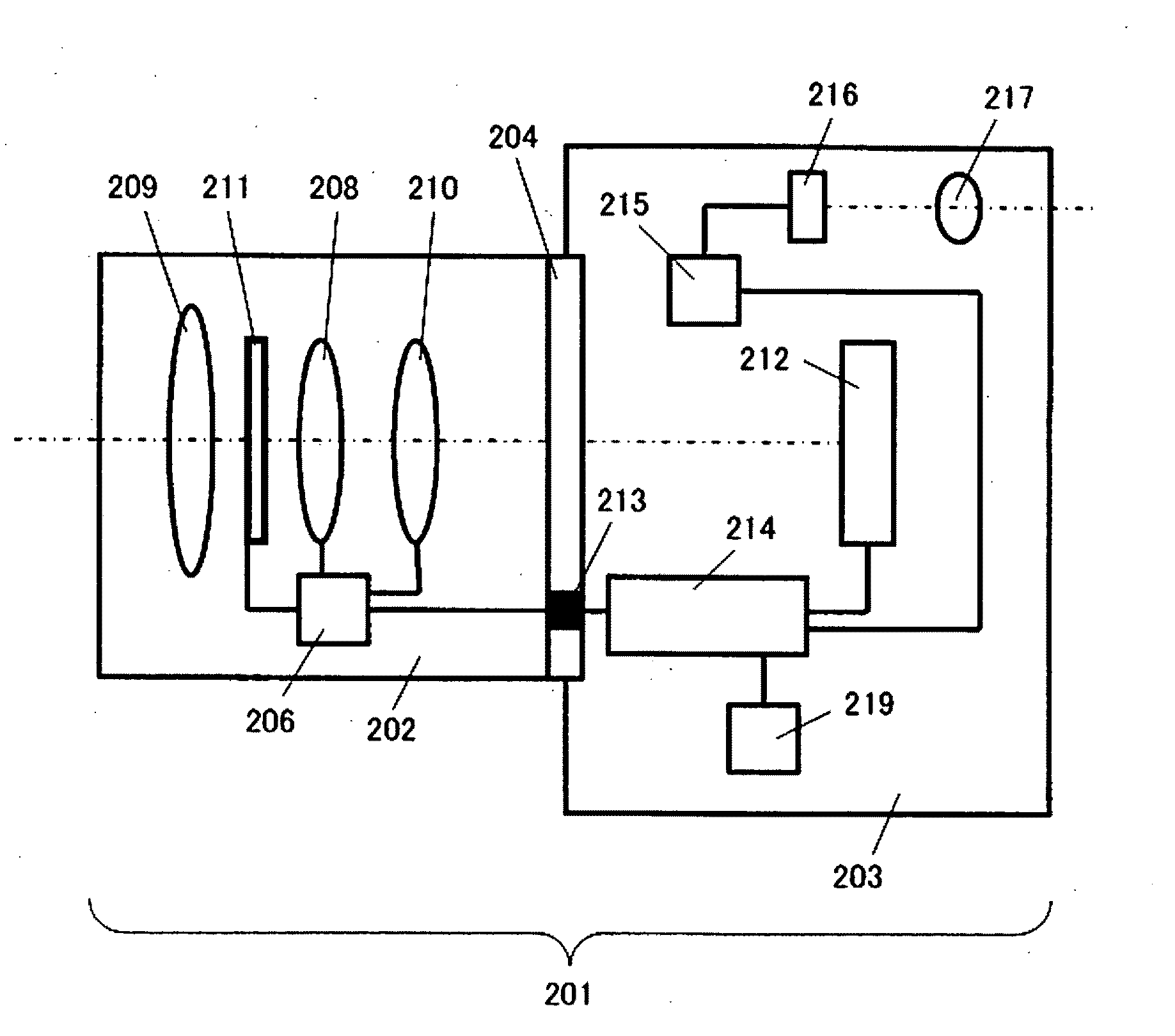
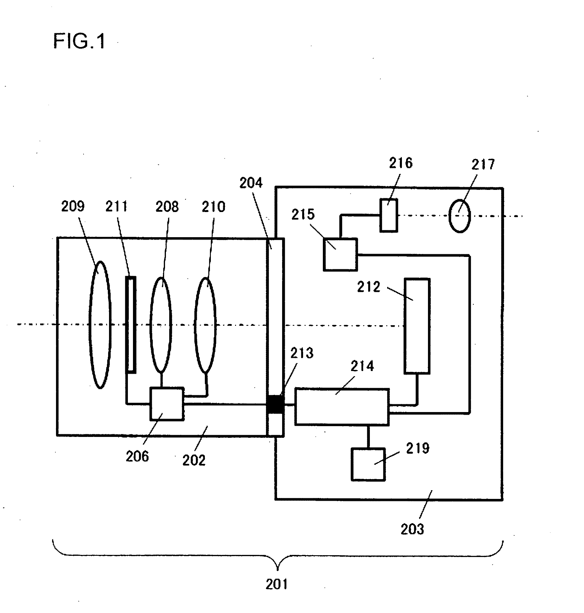
[0054]The image sensor and the image-capturing device achieved in an embodiment of the present invention are now described. FIG. 1 shows in a sectional side view the structure of a digital still camera used in conjunction with interchangeable lenses, which is equipped with the image sensor achieved in the embodiment. A digital still camera 201 in the embodiment includes an interchangeable lens 202 and a camera body 203. The interchangeable lens 202 among various interchangeable lenses is mounted at the camera body 203 via a mount unit 204.

[0055]The interchangeable lens 202 includes a lens 209, a zooming lens 208, a focusing lens 210 an aperture 211 and a lens drive control device 206. The lens drive control device 206, constituted with a microcomputer, a memory, a drive control circuit and the like, none shown engages in communication with a body drive control device 214 to be detailed later to transmit lens information to the body drive control device 214 and receive camera informa...


PUM


Abstract

An image sensor includes: a plurality of image-capturing pixels that, upon each receiving a partial light flux within a predetermined wavelength range, which is part of a photographic light flux used to form an optical image, output image signals corresponding to the optical image; a plurality of focus detection pixels that receive a pair of focus detection light fluxes in a wider wavelength range than the predetermined wavelength range and output a pair of focus detection signals; and a reduction unit that adjusts a signal level of the focus detection signals output from the plurality of focus detection pixels to be equal to or less than a signal level of the image signals each output from one of the plurality of image-capturing pixels under a given light receiving condition.

Description

INCORPORATION BY REFERENCE[0001]The disclosures of the following priority applications are herein incorporated by reference: Japanese Patent Application No. 2008-302972 filed Nov. 27, 2008, Japanese Patent Application No. 2009-031335 filed Feb. 13, 2009, U.S. Provisional Patent Application No. 61 / 202,282, Feb. 13, 2009, and Japanese Patent Application No. 2009-176543 filed Jul. 29, 2009.BACKGROUND OF THE INVENTION[0002]1. Field of the Invention[0003]The present invention relates to an image sensor and an image-capturing device.[0004]2. Description of Related Art[0005]The image-capturing devices known in the related art include that disclosed in Japanese Laid Open Patent Publication No. H1-216306. This image-capturing device includes an image-capturing means achieved by arraying a plurality of focus detection pixels, via which a pair of image signals corresponding to a pair of images formed with a pair of light fluxes passing through an optical system are generated, as part of an arr...

Claims


Application Information

Patent Timeline
Patent Type & Authority Applications(United States)
IPC IPC(8): H04N5/262
CPCH04N9/045H04N5/23212H01L27/14621H01L27/14627H01L27/14623H04N23/672H04N25/704H04N25/611H04N25/134
Inventor KUSAKA, YOSUKESUZUKI, SATOSHI
Owner MAXELL HLDG LTD
Why Eureka
Try Eureka