Tomographic Light Field Microscope

a light field microscope and tomographic technology, applied in the field of medical imaging data analysis, can solve the problems of limited scanning speed of mechanical arrangement and inability to disclose imaging techniques from a plurality of viewpoints

Inactive Publication Date: 2010-07-29
VISIONGATE
View PDF5 Cites 7 Cited by
  • Summary
  • Abstract
  • Description
  • Claims
  • Application Information

AI Technical Summary

Problems solved by technology

Such a mechanical arrangement has limited scanning speed due to limiting factors such as the mass of the objective and speed of the piezoelectric element.
However, Levoy et. al. does not disclose techniques for imaging objects from a plurality of viewpoints.

Method used


Image

  • Tomographic Light Field Microscope
  • Tomographic Light Field Microscope
  • Tomographic Light Field Microscope

Examples


Embodiment Construction

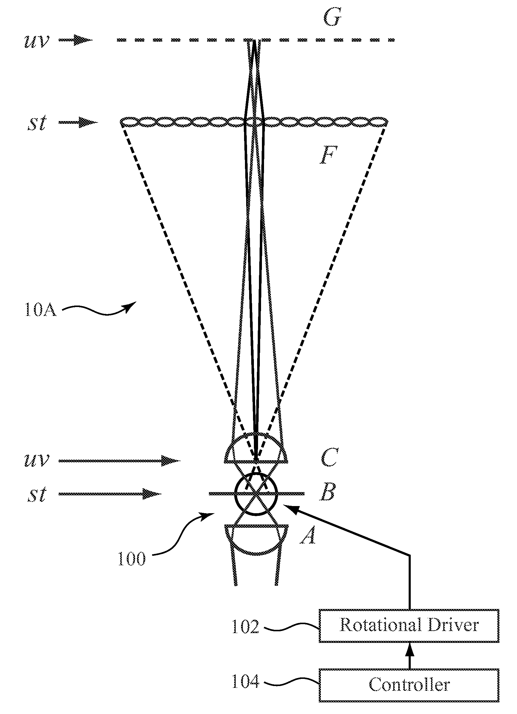
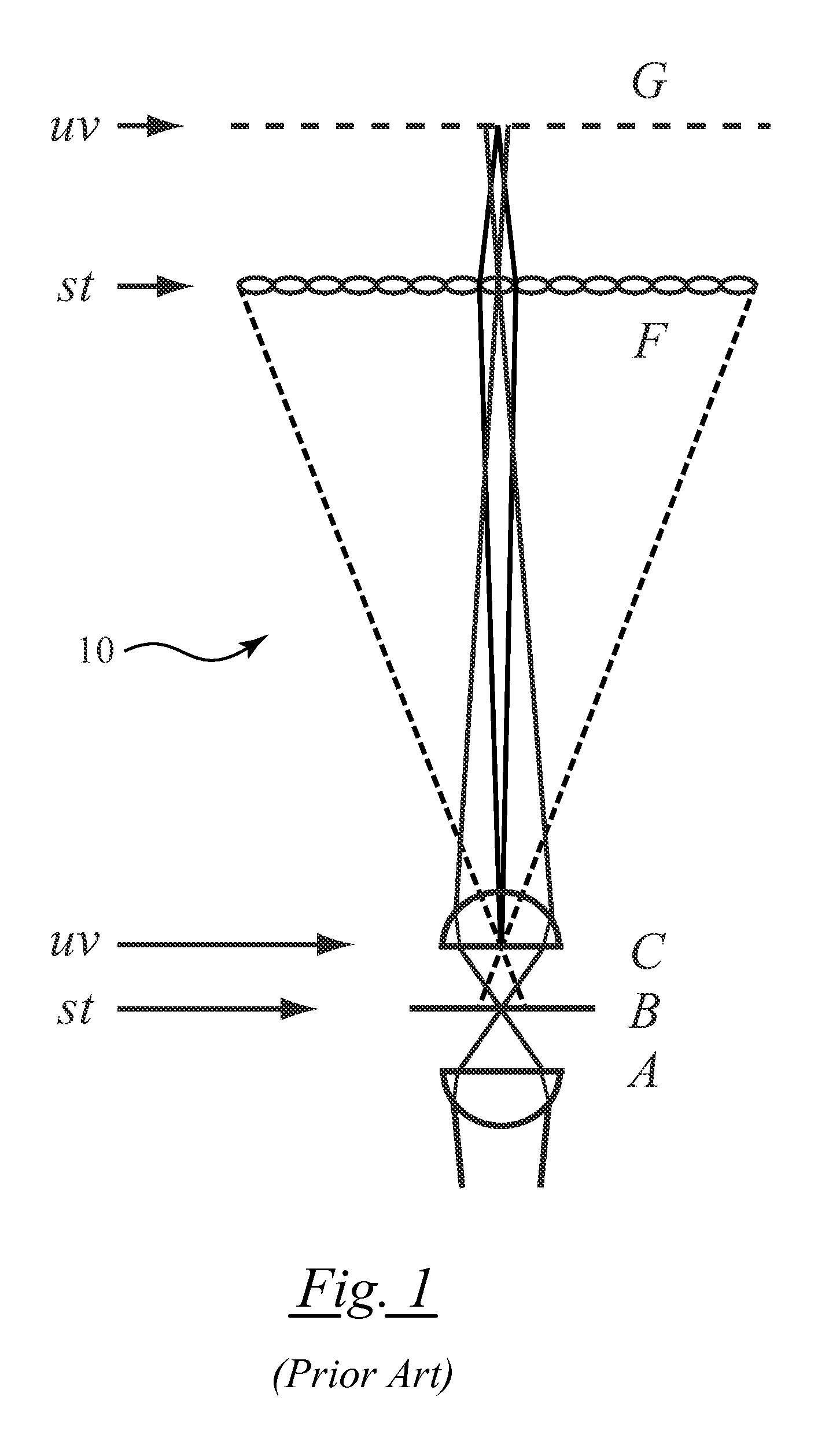
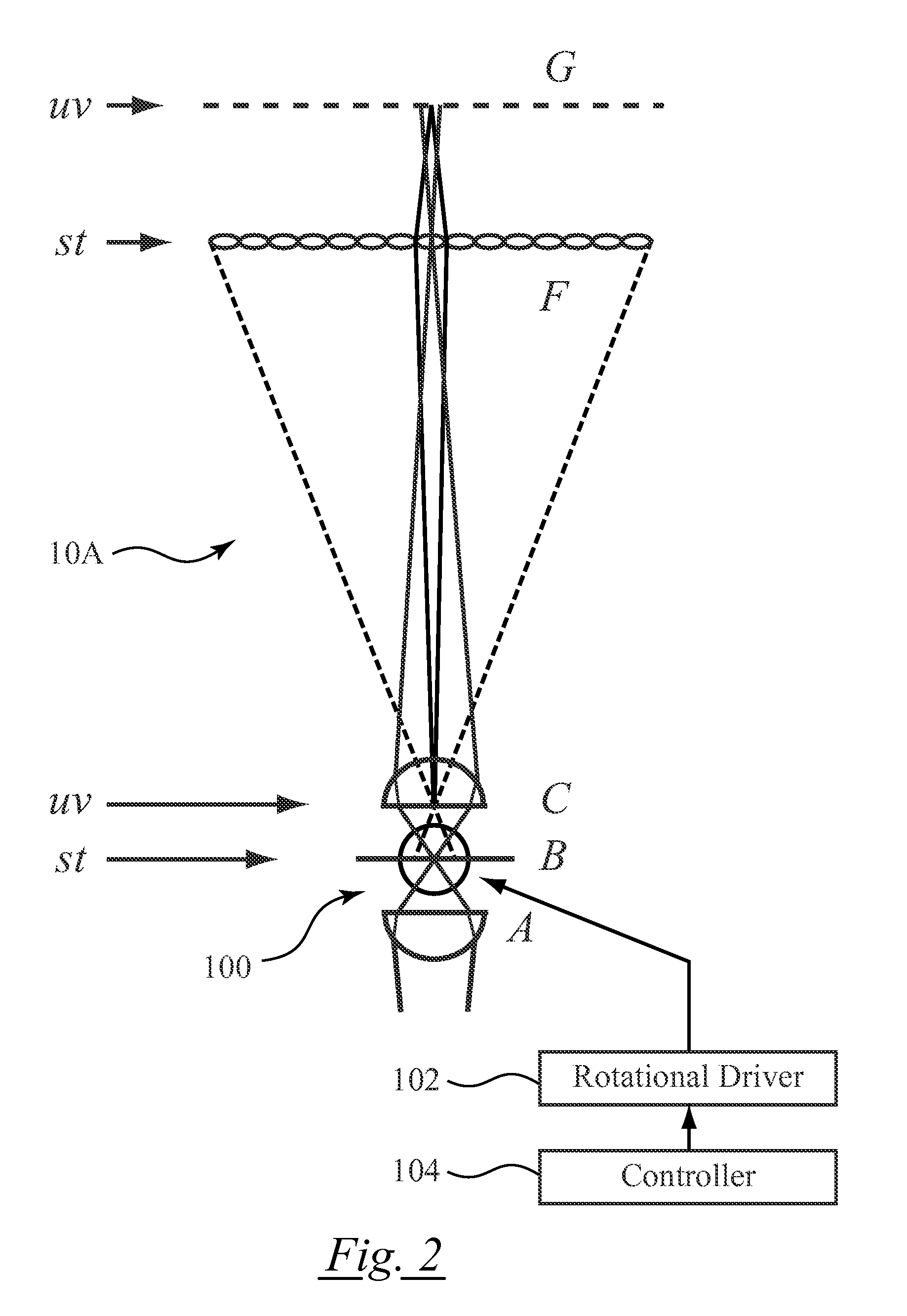
[0010]Referring now to FIG. 2, there shown is one example of an optical tomography system including a light field microscope with a rotating specimen carrier. The optical tomography system includes a light field microscope 10A constructed substantially as described above with respect to FIG. 1. A carrier 100 is adapted to hold a specimen and rotate with respect to the optical z axis so as to present a plurality of is varying viewpoints for imaging by the photosensor array G. In one useful embodiment the specimen carrier may comprise a capillary tube sized to hold a biological cell in a liquid or gel environment, where the liquid or gel is selected for optical properties matching the capillary tube to the lenses in the optical tomography system.

[0011]As compared to the optical tomography system of Fauver et al., the optical tomography system presented herein does not require scanning the objective lens for acquiring pseudoprojections. This reduces system complexity. As compared to a ...


PUM


Abstract

An optical tomography system includes a light field microscope including an objective lens, a computer-controlled light source, a condenser lens assembly and a microlens array aligned along an optical axis. A carrier containing a specimen is coupled to a rotational driver for presenting varying angles of view of the specimen. A photosensor array disposed to receive photons from the objective lens. A computer is linked to control the computer-controlled light source and condenser lens assembly and the rotational driver, and coupled to receive images from the photosensor array where the light field microscope simultaneously captures a continuum of focal planes in the specimen for each of a set of the varying angles of view of the specimen.

Description

RELATED APPLICATIONS [0001]This application hereby claims the benefit of prior filed co-pending U.S. provisional patent application No. 61 / 145,717, filed Jan. 19, 2009, of Mathew D. Watson, entitled “Tomographic Light Field Microscope,” which is incorporated herein by this reference.FIELD OF THE INVENTION[0002]The present invention relates generally to analysis of medical imaging data, and, more particularly to employing a tomographic light field microscope in a biological cell imager.BACKGROUND OF THE INVENTION[0003]In the field of optical tomography continuous scanning from multiple perspectives is used to acquire projection images from, effectively, an infinite number of adjacent focal planes. The focal plane of an optical imaging system is mechanically translated along an axis perpendicular to the focal plane through the thickness of a specimen during a single detector exposure. This is often referred to as “scanning” the focal plane. The process is repeated from multiple perspe...

Claims


Application Information

Patent Timeline
Patent Type & Authority Applications(United States)
IPC IPC(8): G02B21/18
CPCG02B21/086
Inventor WATSON, MATHEW D.
Owner VISIONGATE
Why Eureka
Try Eureka