Carbonization apparatus and method of the same

a carbonization apparatus and negative pressure technology, applied in the direction of chemistry apparatus and processes, chemical/physical/physical/physical-chemical processes, catalysts for physical/chemical processes, etc., can solve the problems of increasing ash and tar, decreasing the degree of carbonization, and difficult removal of non-carbon elements, etc., to achieve the effect of reducing the unexpected reaction between the by-product gas and the raw material, reducing the degree of carbonization, and easy removal

Inactive Publication Date: 2010-07-29
LINKWIN TECH
View PDF10 Cites 3 Cited by
  • Summary
  • Abstract
  • Description
  • Claims
  • Application Information

AI Technical Summary

Benefits of technology

[0013]When the raw material is carbonized in the carbonization chamber, the by-product gas can be removed easily. Therefore, the structure of the carbon layer in the carbon product is much regular than the prior. In other words, the degree of the carbonization is increased.
[0014]Besides, the ash inside the carbonization chamber is fewer. And therefore, the unexpected reaction between the by-product gas and the raw material is decreased. In other words, the degree of the carbonization of the carbon product is increased.
[0015]At least, since the present invention doesn't need lots of nitrogen and the buffering devices prevent the oxygen come from outside to affect the process, the thermal consumption and the inert gas consumption are also decreased.

Problems solved by technology

However, when the carbonization chamber is kept at a positive pressure, the non-carbon elements are difficult to remove and the by-product gas fills the carbonization chamber.
The ash and the tar also increases but the degree of carbonization decreases because non-carbon elements are hard to remove from the raw material under the positive pressure and the un-removed non-carbon elements effects the rearrangement of the carbon layer.

Method used


Image

  • Carbonization apparatus and method of the same
  • Carbonization apparatus and method of the same
  • Carbonization apparatus and method of the same

Examples


Embodiment Construction

[0021]Reference will now be made in detail to the present embodiments of the invention, examples of which are illustrated in the accompanying drawings. Wherever possible, the same reference numbers are used in the drawings and the description to refer to the same or like parts.

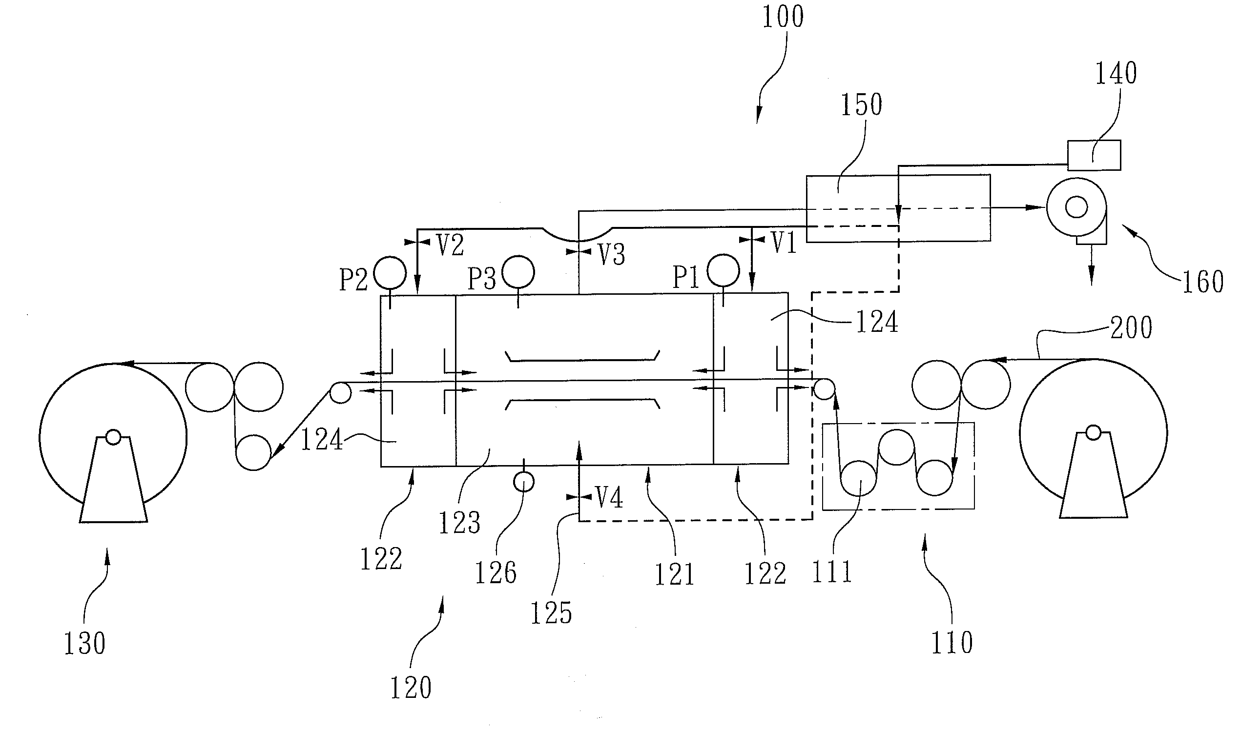
[0022]The continuous negative pressure carbonization apparatus and method of the present invention provides a negative pressure state to the carbonization chamber of the carbonization device. And therefore, the raw material is carbonized in a negative pressure state. The application of the present invention is not limited to producing the woven carbon fabric fiber, and is able to be applied in any continuous carbonization process. To describe the present invention clearly, the embodiments take the woven fiber fabric for instance.

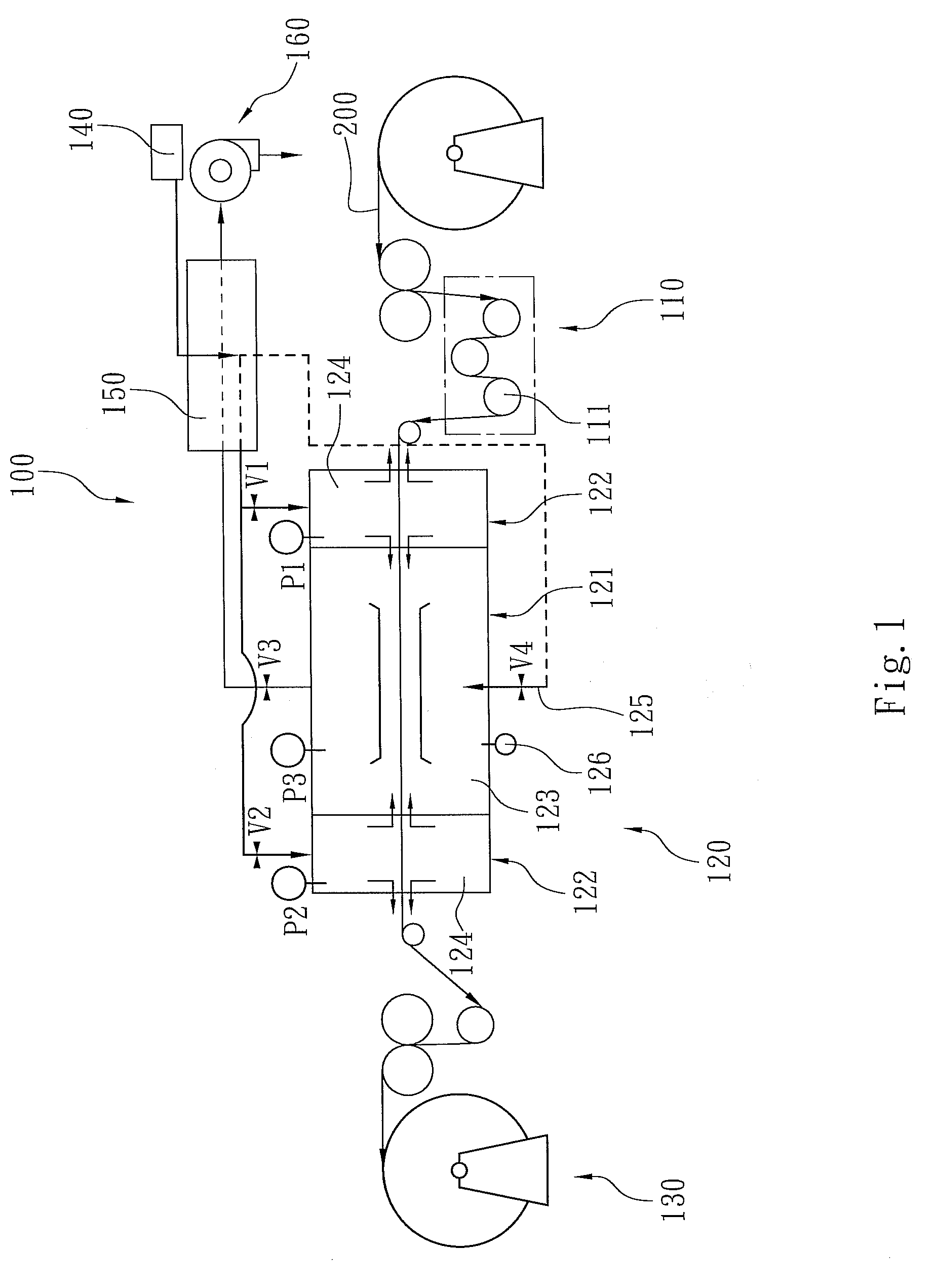
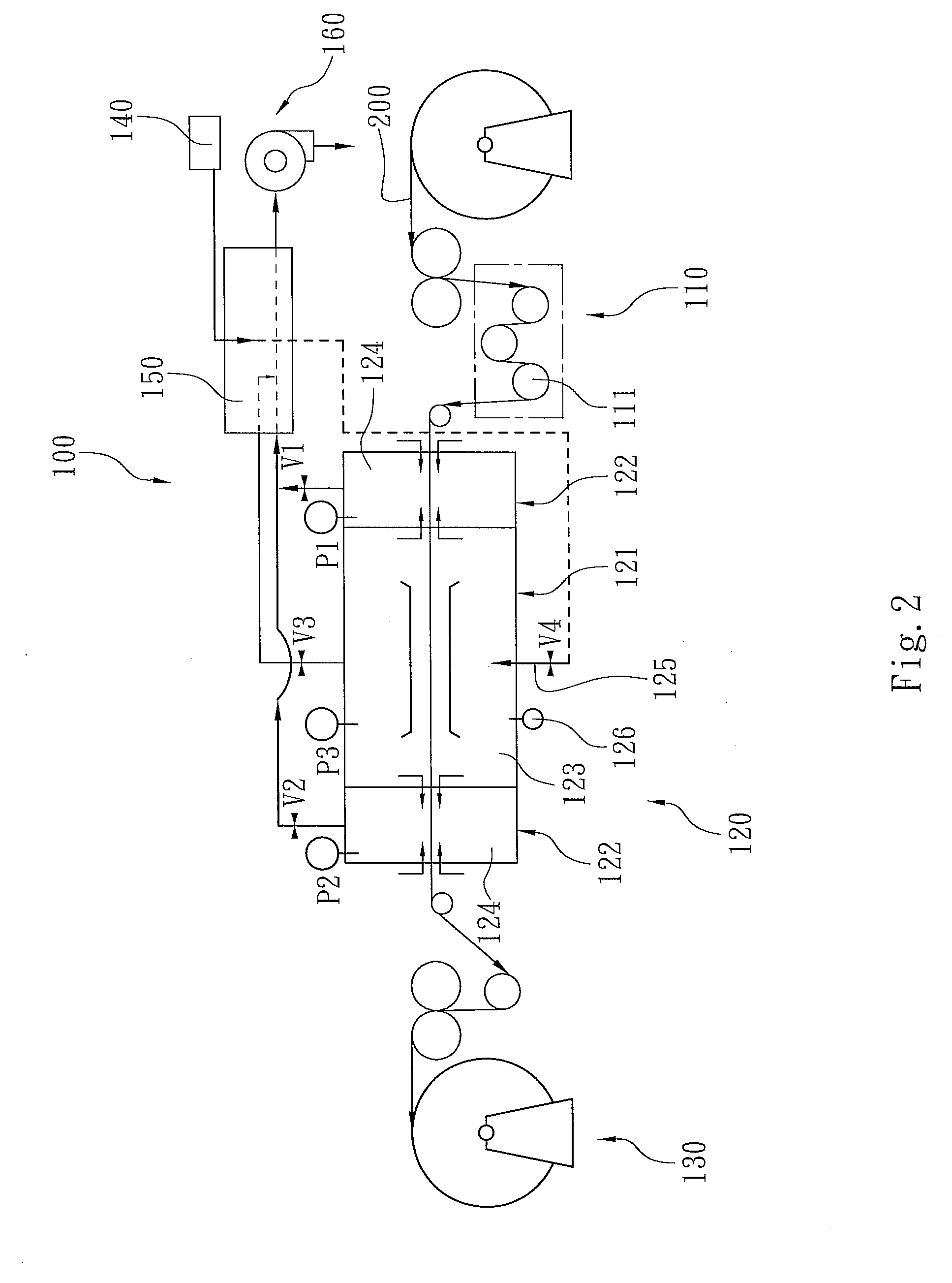
[0023]Please refer to FIG. 1 for the first embodiment of the present invention. The carbonization apparatus 100 includes a material feeding device 110, a carbonizing chamber 120, a mat...


PUM

PropertyMeasurementUnit
temperatureaaaaaaaaaa
pressureaaaaaaaaaa
pressureaaaaaaaaaa

Abstract

A continuous negative pressure carbonization apparatus includes a material feeding device, a carbonizing chamber and a material collecting device. The material feeding device feeds the raw material. The carbonizing chamber receives and carbonizes the raw material and it includes a carbonization device and two buffering devices. The carbonization device has a carbonization chamber. The carbonization chamber has a material inlet and a material outlet. The buffering devices are respectively mounted and connected to the material inlet and the material outlet. The material collecting device collects the carbonized product from the carbonization chamber. When the raw material is carbonized in the carbonization chamber, the pressure of the carbonization chamber is kept at a negative pressure state smaller than the atmospheric pressure.

Description

BACKGROUND[0001]1. Field of Invention[0002]The present invention relates to a continuous negative pressure carbonization apparatus and the method of the same, and particularly relates to a continuous carbonization apparatus that executes the carbonization process in the negative pressure condition and method thereof.[0003]2. Description of Related Art[0004]The application of the carbonization apparatus is very popular in applications such as the production of woven carbon fiber fabric. The continuous carbonization apparatus and the prior method heats the carbonization chamber and infuse a large volume of inert gas, such as nitrogen (N2), which will not react with the material. Therefore, when the raw material, fabric, is carbonized in the carbonization chamber, the inert gas prevents the raw material from touching and reacting with the oxygen in the air. And then, the non-carbon elements of the raw material are removed in the high temperature carbonization process. Finally, the raw ...

Claims


Application Information

Patent Timeline
Patent Type & Authority Applications(United States)
IPC IPC(8): C01B31/02B01J19/00
CPCD01F9/32C01B31/02C01B32/05
Inventor HU, CHUNG-HUALEE, KUO-TING
Owner LINKWIN TECH
Why Eureka
Try Eureka