Endovascular cerebrospinal fluid shunt

a cerebrospinal fluid and endovascular technology, applied in the field of endovascular shunts, can solve problems such as inability, and achieve the effect of more physiologic drainage of cerebrospinal fluid

Inactive Publication Date: 2010-07-29
TUFTS MEDICAL CENTER INC
View PDF9 Cites 39 Cited by
  • Summary
  • Abstract
  • Description
  • Claims
  • Application Information

AI Technical Summary

Benefits of technology

[0010]The endovascular cerebrospinal fluid shunt of the present invention is an improvement over the standard cerebrospinal fluid shunts because it can be placed into a patient percutaneously via a catheter inserted into the venous system of the body through a needle hole, without the need for open surgery and the skin incisions required with current shunt devices. In some patients, the device can be inserted without general anesthesia, which is not possible with current cerebrospinal fluid shunts. The device also will allow for more physiologic drainage of cerebrospinal fluid since the device is shunting cerebros

Problems solved by technology

In some patients, the device can be inserted without general anesth

Method used


Image

  • Endovascular cerebrospinal fluid shunt
  • Endovascular cerebrospinal fluid shunt
  • Endovascular cerebrospinal fluid shunt

Examples


Embodiment Construction

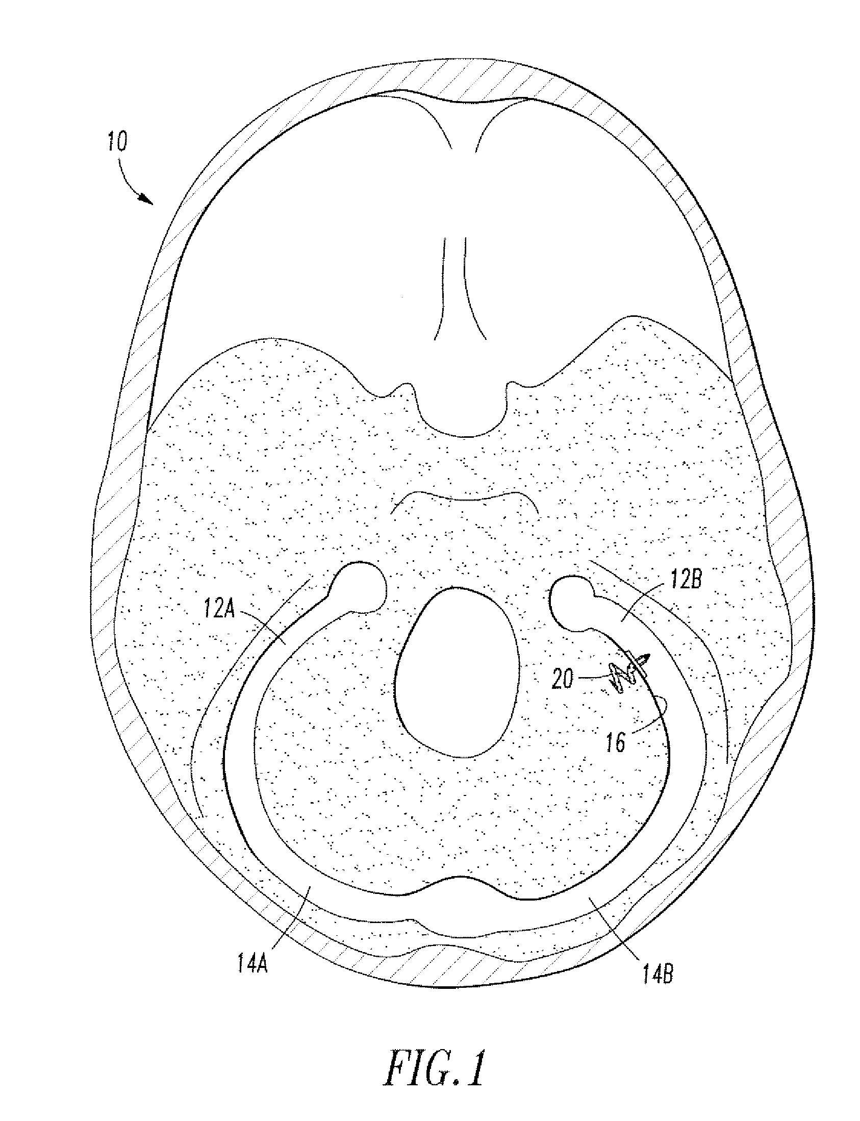
[0019]Referring to FIG. 1, the endovascular shunt device of the present invention can be delivered to the right or left sigmoid sinus 12A, 12B of a patient's skull 10 via either the right or left jugular vein respectively of the venous system. The sigmoid sinus lumen 12 is located between the temporal bone (FIGS. 3-5) and the cerebellum.

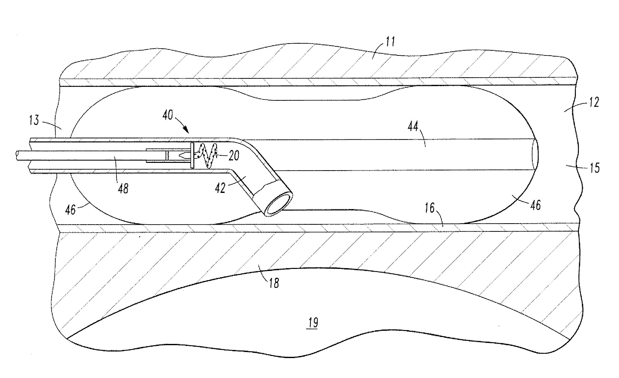
[0020]A shunt 20 is implanted into a sigmoid sinus wall 16, so that one end communicates with CSF located in the cistern or CSF space 18 around the cerebellum 19. The device of the present invention uses the body's natural disease control mechanisms by delivering the CSF from cistern 18 into sigmoid sinus lumen 12 of the venous system. The venous system of the patient can be accesses either through the femoral or jugular veins (not shown) percutaneously. It should be appreciated that the shunt device of the present invention can be delivered to the sigmoid sinus via other locations.

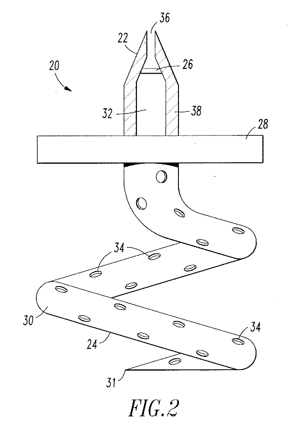
[0021]As shown in FIG. 2, one embodiment of the endovascular CSF shun...


PUM


Abstract

An implantable shunt device for draining cerebrospinal fluid from a patient's subarachnoid space. The device includes a shunt having opposed first and second ends. A one-way valve is located at the first end of the shunt. A helical tip is disposed at the second end. The helical tip is constructed to penetrate a sinus wall of the patient. Upon implantation, a hollow passageway extends between the helical tip and one-way valve such that fluid can be drained through the helical tip and out through the valve. The endovascular cerebrospinal fluid shunt of the present invention can be placed into a patient percutaneously via a catheter inserted into the venous system of the body through a needle hole, without the need for open surgery and the skin incisions required with current shunt devices. The device also allows for more physiologic drainage of cerebrospinal fluid since the device is shunting cerebrospinal fluid into the same cerebral venous system that occurs naturally in normal people.

Description

BACKGROUND OF THE INVENTION[0001]1. Field of the Invention[0002]The present invention relates to an endovascular shunt implantable into the wall of a patient's sigmoid sinus, and more particularly, to a shunt capable of draining cerebrospinal fluid from the patient's subarachnoid space to the venous system.[0003]2. Description of the Related Art[0004]It is known to treat hydrocephalus by draining cerebrospinal fluid (CFS) from the brain with a drain tube, catheter or shunt. See U.S. Pat. Nos. 5,385,541 and 4,950,232. These known devices are complex and invasive. The risk for infection is also increased due to the complexity of these devices.[0005]The known shunts are limited to areas of placement due to fluid flow control. Moreover, the known shunts and methods of placements do not work in conjunction with a body's natural disease control processes. Accordingly, in recent years exploration of placement of a catheter or shunt in the venous sinus of a patient has been explored. See U....

Claims


Application Information

Patent Timeline
IPC IPC(8): A61M1/00
CPCA61M27/006A61F2230/0091A61M25/0075A61M27/002A61M2025/0076A61M2202/0464A61M2205/0238A61M2210/0687A61M2210/0693A61M2210/12
Inventor HEILMAN, CARL
Owner TUFTS MEDICAL CENTER INC
Why Eureka
Try Eureka