Illuminated Intravascular Blood Filter

a technology of intravascular blood filter and light source, which is applied in the field of medical devices, can solve the problems of increasing the cost of hospital and patient, increasing the complexity of the procedure, and affecting the quality of life of the surrounding tissue, so as to limit the possibility of entanglement

Inactive Publication Date: 2010-07-29
BOSTON SCI SCIMED INC
View PDF99 Cites 51 Cited by
  • Summary
  • Abstract
  • Description
  • Claims
  • Application Information

AI Technical Summary

Benefits of technology

[0016]One method of filtering the carotid arteries leaving the aorta free from obstruction is to deliver a filter to each of the carotid arteries from the groin leaving them in the carotid vasculature and retrieving them via snare post procedure. A delivery catheter would be inserted through an introducer in the groin (femoral artery) and delivered to the common carotid arteries and detached. The delivery catheter would be removed and a second filter would be delivered in a similar manner to the other carotid artery. With two detached filters now in place the procedure treating the aortic or mitral valve can now be completed with embolic protection for the cerebral vascular system. Once the procedure to the valve is completed, the filters can be snared and retrieved back out the femoral artery as they were delivered. Any embolic particles will be captured in the filter device and removed safely from the body.
[0017]Another method for filtering the carotid arteries would be to deliver a filter from the femoral artery and utilize a single catheter to house the two attachment means to the filters. These attachments may be a wire similar to a guidewire or a hypo-tube to connect the filter element to an external portion of the body. Keeping these wires or connection means organized and contained within a single or dual lumen catheter will help organize and limit potential entanglement with other catheters being delivered to the target site such as the aortic valve or other cardiac elements including but not limited to the mitral valve and coronary arteries. The distal portion of the catheter may have a single exit portion or a staggered exit to allow an exit at different points along the catheter. One exit port may be at the distal most end of the catheter and the other may be a centimeter proximal from this to allow the attachment wire to exit near the left common carotid artery. Furthermore, there could be an extension to the distal most portion of the catheter allowing side ports for both wires to exit. This would allow for additional catheter stabilization within the aorta.
[0020]Another means to deliver the filters via radial artery approach would be to utilize a dual lumen catheter where each lumen would house a single filter. The first lumen would deliver a filter to the left carotid artery and the second lumen would deliver a filter to the right carotid artery. The lumens could be staggered in length to reach each ostium in which case the first or left filter lumen would be longer in length to allow for placement distal from the second filter placement in the right carotid. Additionally, the second lumen may be pre-shaped with a curve to allow easy access to the right carotid artery. This pre-shaped curve may be retained in a straighter manner to allow for delivery and released to express the delivery shape when at the bifurcation of the subclavian and the carotid artery. Furthermore, there may be an active shaping where the curve is directed external to the body by a handle mechanism such as a pull-wire where tension would generate a compressive force to the catheter column preferentially bending the lumen. Recovery could utilize the same dual lumen concept or utilize a second recovery sheath independently from one another.
[0021]Another application for this device and method would be for surgical operations where the patient may be put on heart-lung bypass. During cross clamping of the aorta catheters or wires in the aorta may interfere with the procedure and allow leakage of blood around the cannulas used. If any of the above described devices or techniques are used before the patient's chest is opened this filtration of the carotid vessels would protect from emboli thus reducing the stroke risk during and after the procedure. Additional antithrombotic coatings to the filter could allow for an extended implantation time allowing filtration time to be extended post procedure. An example of this coating would be Heparin. Placement of these catheters and filters could be under fluoroscopy or ultrasound guidance to direct proper filter placement. Radiopaque markers may add necessary visibility to the catheter, filter and or wires.

Problems solved by technology

This particulate may travel downstream and cause obstruction to distal vessels starving them of oxygenated blood and the surrounding tissue may die quickly without proper blood flow.
This would add to the complexity of the procedure and also add additional cost to the hospital and patient.

Method used


Image

  • Illuminated Intravascular Blood Filter
  • Illuminated Intravascular Blood Filter
  • Illuminated Intravascular Blood Filter

Examples


Embodiment Construction

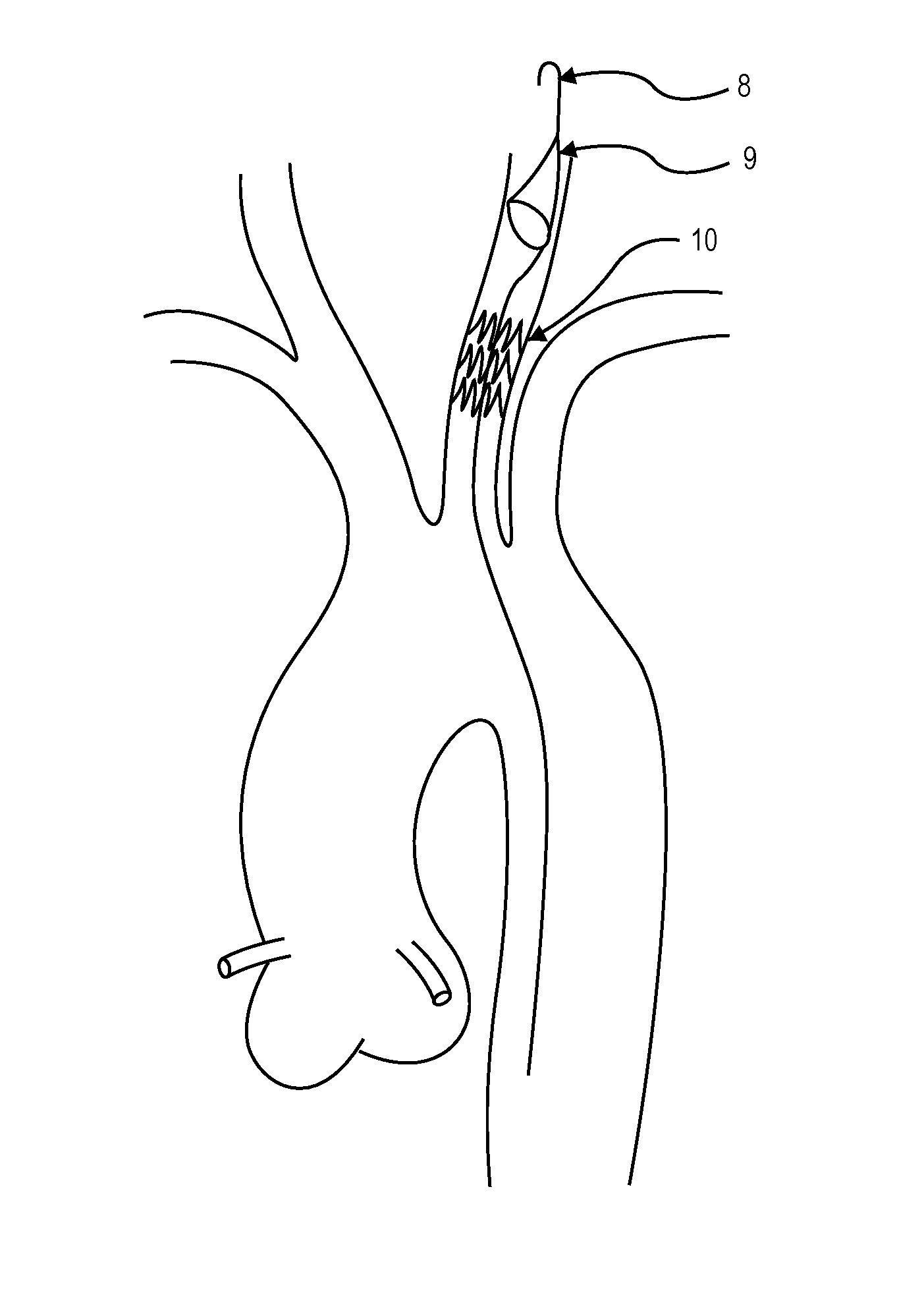
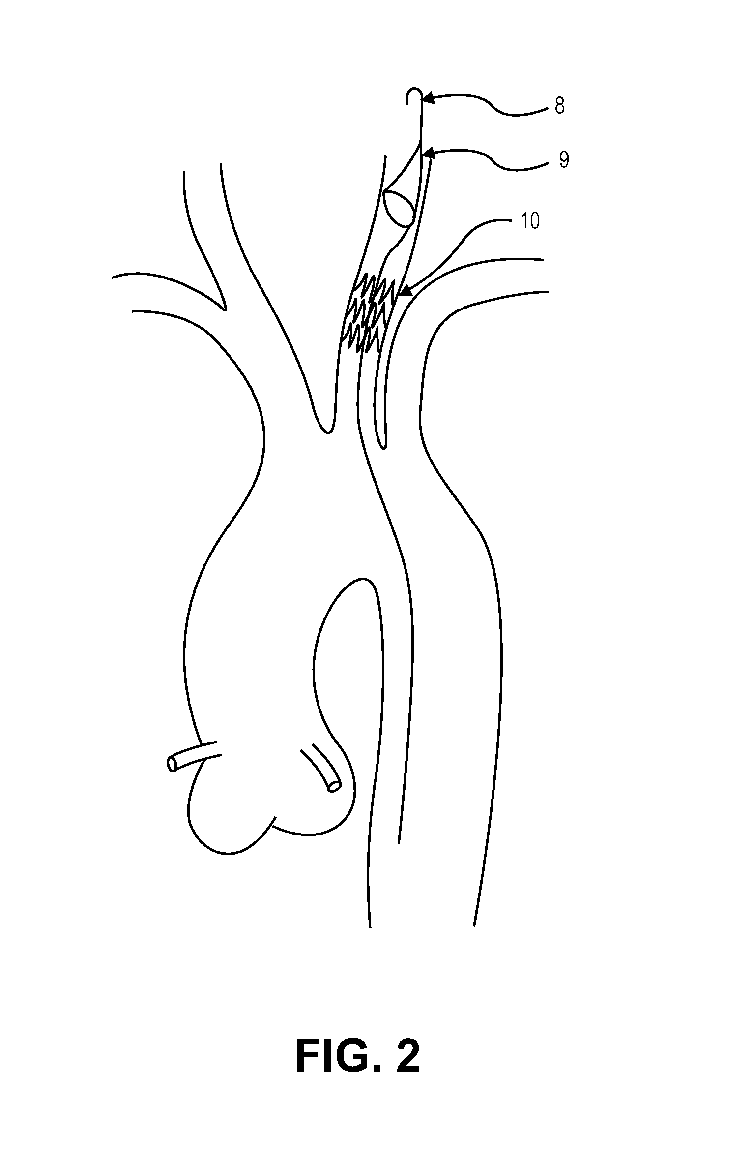
[0052]The invention described herein is an intravascular filter introduced to the aorta at or near the aortic cannulation site. The device would be illuminated for guidance and have a relatively short overall length (10 to 40 cm). Any of the common intravascular filter devices could be used to complete the filtration of the blood but would need to have an illumination of some portion to guide the delivery to the carotid vessels. Introduced through a purse-string suture, the devices would measure about 1 to 4 millimeters in diameter and be delivered through a 5 or 6 French introducer over a guidewire where the introduction site would be the same as the cannula introduction site between the purse string sutures. Sheathed in a delivery catheter the filters would be exposed to the vessel in a collapsed state and advanced out the end of the delivery catheter where they would expand either passively by a memory metal such as Nitinol or actively by a balloon expansion or other radial force...


PUM


Abstract

Disclosed is a novel filter and delivery means. The device described within will not interfere with standard practice and tools used during standard surgical procedures and tools such as cannulas, clamps or dissection instruments including valve replacement sizing gauges or other surgical procedures where the patient must be put on a heart-lung machine cross-clamping the aorta.

Description

CROSS REFERENCE TO RELATED APPLICATIONS[0001]This application claims the benefit under 35 U.S.C. 119 of U.S. Provisional Patent Application No. 61 / 148,054, filed Jan. 29, 2009, titled “Illuminated Intravascular Blood Filter.” This application is herein incorporated by reference in its entirety.INCORPORATION BY REFERENCE[0002]All publications and patent applications mentioned in this specification are herein incorporated by reference to the same extent as if each individual publication or patent application was specifically and individually indicated to be incorporated by reference.BACKGROUND OF THE INVENTION[0003]This invention relates generally to medical devices used during vascular intervention, and more particularly, concerns medical devices that are useful in treating aortic valve replacement, thromboembolic disorders and for removal of foreign bodies in the vascular system.[0004]Thromboembolic disorders, such as stroke, pulmonary embolism, peripheral thrombosis, atherosclerosi...

Claims


Application Information

Patent Timeline
Patent Type & Authority Applications(United States)
IPC IPC(8): A61F2/01
CPCA61F2/013A61F2/2436A61F2002/018A61F2230/0069A61F2230/0008A61F2230/0067A61F2230/0006A61F2/0105A61F2/012
Inventor LASHINSKI, RANDALL T.
Owner BOSTON SCI SCIMED INC
Why Eureka
Try Eureka