Gas turbine combustor

a combustor and gas turbine technology, applied in the direction of machines/engines, combustion types, lighting and heating apparatus, etc., can solve the problems of high cost and complicated sectional shape of the main nozzle b>53/b>, and achieve the effects of reducing design and manufacturing costs, suppressing thermal stress, and simple structur

Active Publication Date: 2010-08-05
MITSUBISHI POWER LTD
View PDF7 Cites 13 Cited by
  • Summary
  • Abstract
  • Description
  • Claims
  • Application Information

AI Technical Summary

Benefits of technology

[0020]According to the first aspect of the invention, the central tube, the outer tube, and the support tube are each formed independently. Thus, the clearance becoming the insulating air layer can be formed between the support tube and the outer periphery of the central tube by a simple structure. Hence, the influence of combustion air flowing around the main nozzle can be suppressed to prevent the coking of oil fuel. If the central tube vibrates, moreover, its vibration can be stopped by the support tube. In addition, when the main nozzle is designed and manufactured, its balance of heat input need not be taken into consideration. This makes it possible to reduce the costs of designing and manufacturing.
[0021]According to the second aspect of the invention, the main nozzle is structured such that the fluid force of gas fuel supplied to the main nozzle does not directly act on the central tube, whereby the vibration of the central tube can be prevented, and the flow of the inflowing gas fuel can be kept unimpeded.
[0022]According to the third aspect of the invention, the coiled bend can accommodate thermal elongation in the central tube and suppress thermal stress. As a result, unlike the conventional technology, the O ring becomes unnecessary, thus decreasing the number of the components, simplifying the structure, reducing the manufacturing cost, and enhancing the maintainability.

Problems solved by technology

In particular, the sectional shape of the main nozzle 53 is complicated.
This has been a major factor for the high cost.

Method used


Image

  • Gas turbine combustor
  • Gas turbine combustor
  • Gas turbine combustor

Examples


embodiment 1

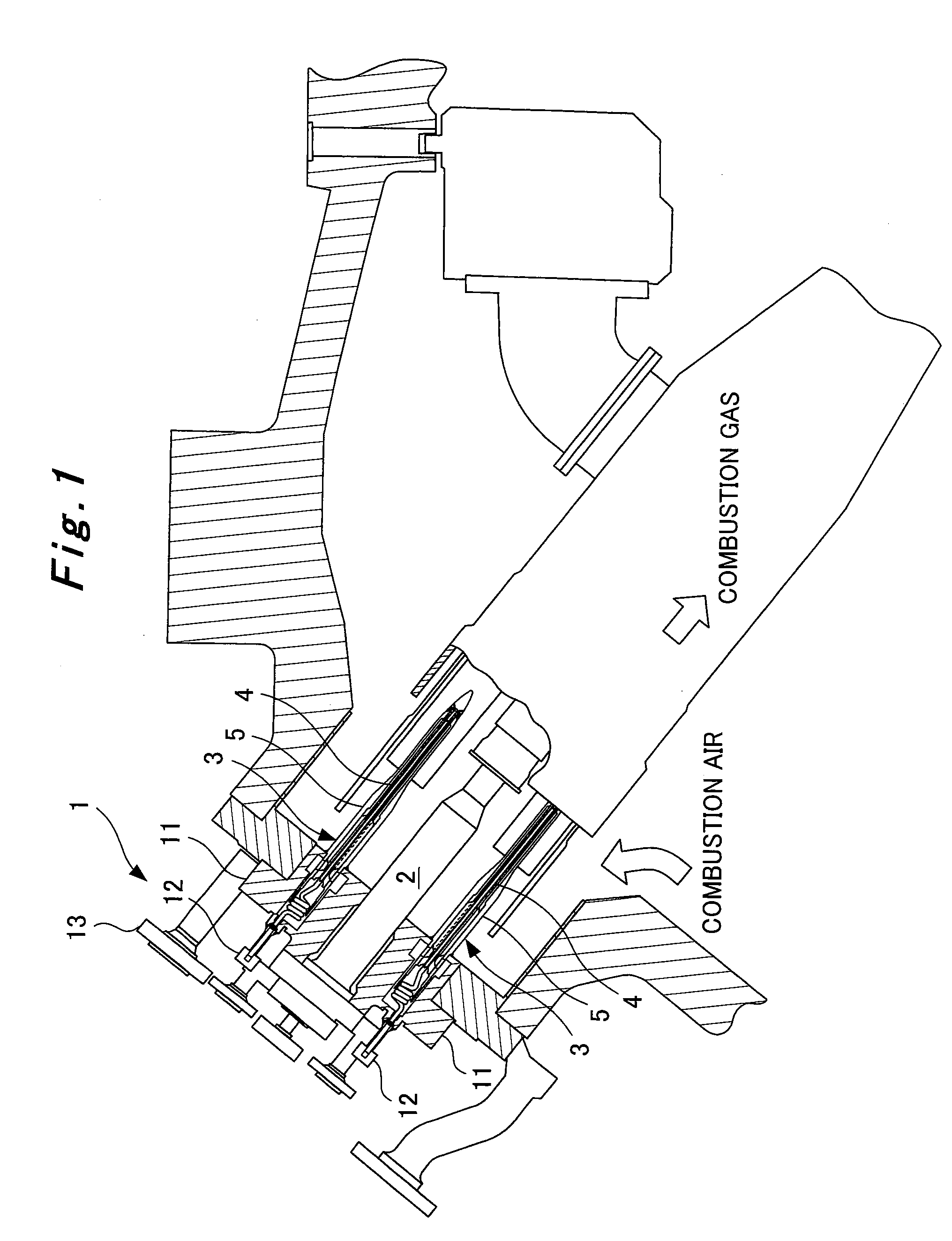
[0038]FIG. 1 is a schematic view showing an embodiment of a gas turbine combustor according to the present invention. In the present embodiment as well, a plurality of combustors 1 of a gas turbine are mounted annularly around a casing of the gas turbine, as in the conventional technology. The combustor 1 is in a dual mode capable of switching between oil fuel and gas fuel. As shown in FIG. 1, the combustor 1 has a pilot nozzle 2, and a plurality of (for example, eight) main nozzles 3 arranged annularly around the pilot nozzle 2. Both the pilot nozzle 2 and the main nozzle 3 are of a structure having an oil fuel path for passage of oil fuel and a gas fuel path for passage of gas fuel.

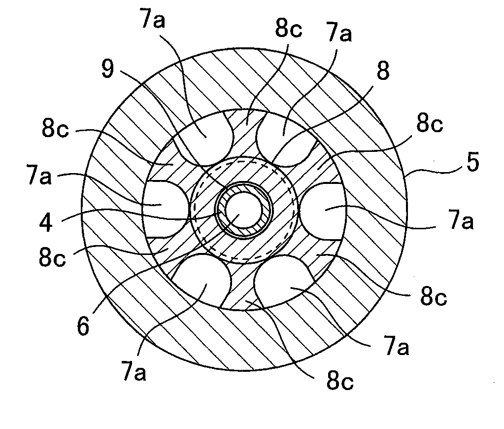
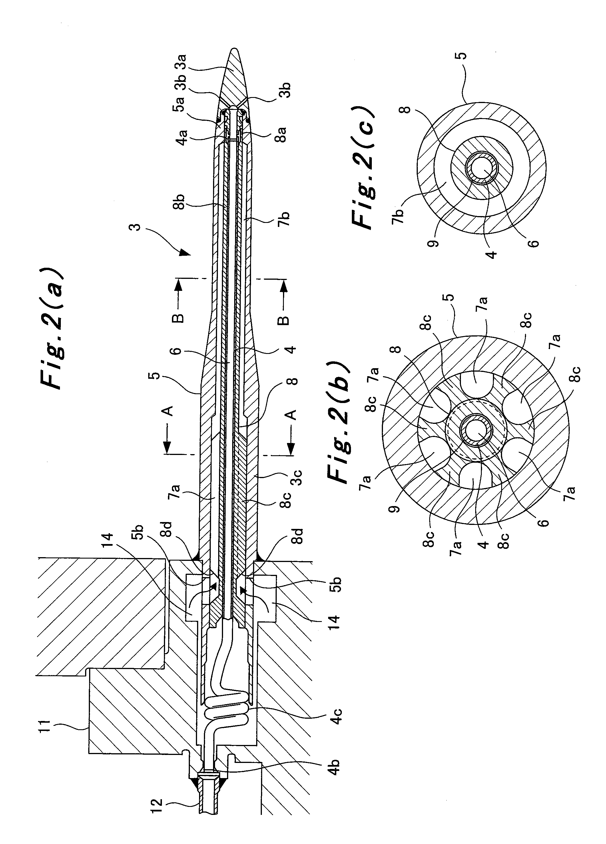
[0039]FIGS. 2(a) to 2(c) are sectional views for illustrating the structure of the main nozzle 3 of the present embodiment. FIG. 2(b) is a sectional view taken on line A-A in FIG. 2(a), and FIG. 2(c) is a sectional view taken on line B-B in FIG. 2(a).

[0040]As shown in FIGS. 2(a) to 2(c), the main nozzle...


PUM


Abstract

An object is to provide a low cost gas turbine combustor. The gas turbine combustor comprises main nozzles (3) each having a cylindrical central tube (4) using an interior thereof as an oil fuel path (6) through which oil fuel flows, a cylindrical outer tube (5) disposed on an outermost periphery of the main nozzle (3), and a support tube (8) disposed between the central tube (4) and the outer tube (5), the central tube (4), the outer tube (5) and the support tube (8) each being formed independently. The support tube (8) has such an internal diameter as to form a clearance becoming an insulating air layer (9) between the support tube (8) and an outer periphery of the central tube (4), and includes a plurality of supporting portions (8c) formed on an axially upstream side and radially contacting an inner periphery of the outer tube (5), a plurality of groove portions (7a) formed along an axial direction between the supporting portions (8c), and a cylindrical portion (8b) formed on an axially downstream side and having an external diameter equal to or smaller than an external diameter of the groove portions (7a). Spaces formed by the outer tube (5) and the groove portions (7a), and a space formed by the outer tube (5) and the cylindrical portion (8b) are used as the gas fuel path in which gas fuel flows.

Description

TECHNICAL FIELD [0001]This invention relates to a gas turbine combustor.BACKGROUND ART [0002]A plurality of combustors of a gas turbine are mounted annularly around a casing of the gas turbine. As shown in FIG. 3, a conventional combustor 51 has a pilot nozzle 52, and a plurality of main nozzles 53 arranged annularly around the pilot nozzle 52. In the case of a dual mode in which fuel is switched between oil fuel and gas fuel, the main nozzle 53 is of a structure having a path for passage of oil fuel and a path for passage of gas fuel. The pilot nozzle 52 also has a similar structure.[0003]Patent Document 1: U.S. Pat. No. 4,258,544[0004]Patent Document 2: Japanese Patent No. 3495730DISCLOSURE OF THE INVENTION Problems to be solved by the invention[0005]FIGS. 4(a) and 4(b) show details of the conventional main nozzle 53. FIG. 4(a) is a sectional view in the axial direction of its leading end side, and FIG. 4(b) is a sectional view taken on line C-C in FIG. 4(a).[0006]As described abo...

Claims


Application Information

Patent Timeline
Patent Type & Authority Applications(United States)
IPC IPC(8): F23R3/36F02C7/22
CPCF23R3/36F23D14/78F23D17/002F23R3/283F23R3/286
Inventor TERADA, YOSHITAKAKONISHI, TETSUOMAE, KATSUYOSHI
Owner MITSUBISHI POWER LTD
Why Eureka
Try Eureka