Pneumatic tire

a pneumatic tire and tire side technology, applied in the field of pneumatic tires, can solve the problems of affecting the temperature rise of the pneumatic tire is not favorable in view of durability, and the use of the reinforcement member may exert adverse effects on the ordinary performance of the tire, so as to increase the travelling resistance, and reduce the temperature of the tire side

Active Publication Date: 2010-08-05
BRIDGESTONE CORP
View PDF13 Cites 16 Cited by
  • Summary
  • Abstract
  • Description
  • Claims
  • Application Information

AI Technical Summary

Benefits of technology

[0074]For the purpose of finding effective arrangement of the turbulence generation ridges 20 as means for lowering tire temperature, detailed analysis was conducted on the air flow while the tire was rolling. The analysis revealed the following facts. Firstly, the air flowed along the tire-circumferential direction but in the opposite direction to the tire-rolling direction. In addition, by the influence of the centrifugal force generated by the rolling of the tire, another air flow was observed from the inner side in the tire-radial direction (from the edge of the opening that was in contact with the rim) outwards in the tire-radial direction (towards the tread portion 2).
[0075]On the basis of the result of the air-flow analysis done in the above described manner, an examination was conducted to find adequate arrangement, in the tire-radial direction, of the turbulence generation ridges 20. The examination revealed the following fact. Provided that each turbulence generation ridge 20 has a given, equal sidewall area (the sidewall area refers to the area of the sidewall of each turbulence generation ridge 20 raised from the surface of the corresponding tire side portion 3, and here, refers to the projected area obtained when the sidewall is seen in particular in the tire-circumferential direction), arranging the turbulence generation ridges 20 more densely on the inner side in the tire-radial direction than on the outer side in the tire-radial direction was more effective in terms of lowering the temperature of the tire side portions 3 than otherwise. This is because of the following reasons.
[0076]Specifically, by arranging the turbulence generation ridges 20 on the inner side in the tire-radial direction, the turbulence is accelerated in the upstream side of the air flow while

Problems solved by technology

Generally, rise in temperature of a pneumatic tire is not favorable in view of the durability because the temperature rise accelerates over-time changes such as the changes in the properties of a material for the pneumatic tire or causes a break of a tread thereof during a high speed run.
This raises the temperature of this portion to a very high temperature, thereby affecting significantly the durability.
In this case, however, the use of the reinforcement member may exert

Method used


Image

  • Pneumatic tire
  • Pneumatic tire
  • Pneumatic tire

Examples


embodiment 1

[0037]A pneumatic tire according to Embodiment 1 will be described in detail below by referring to the drawings.

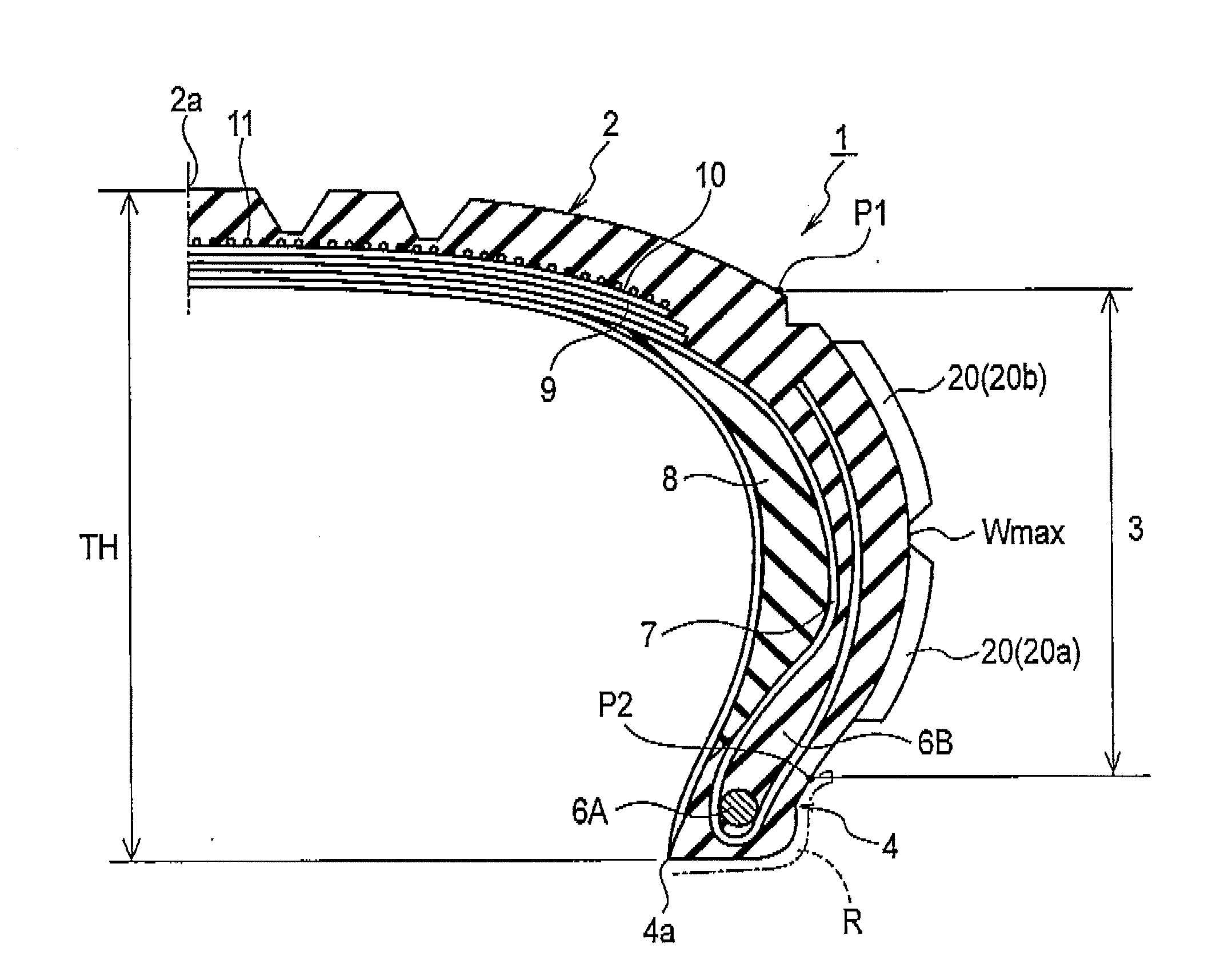
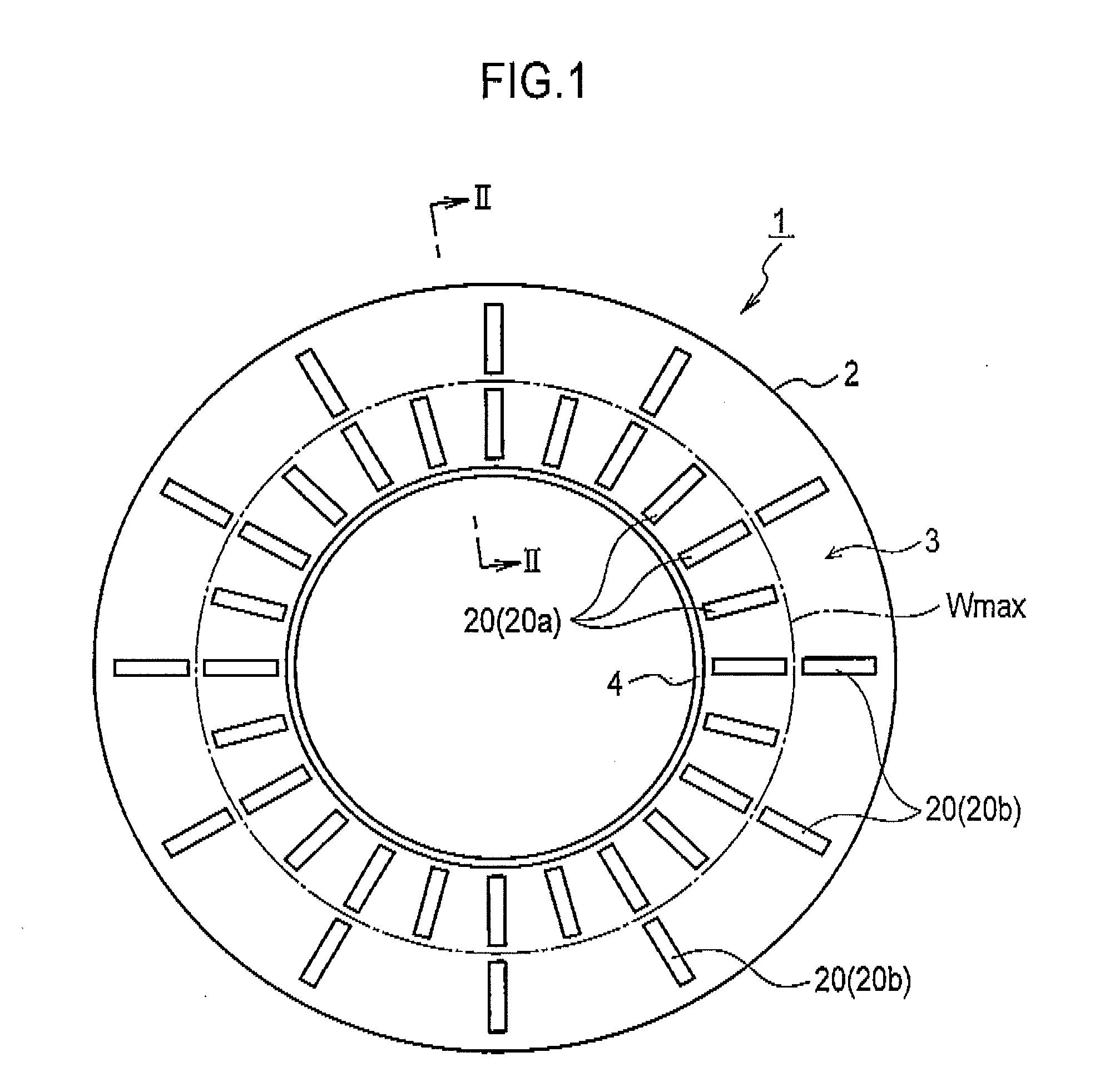
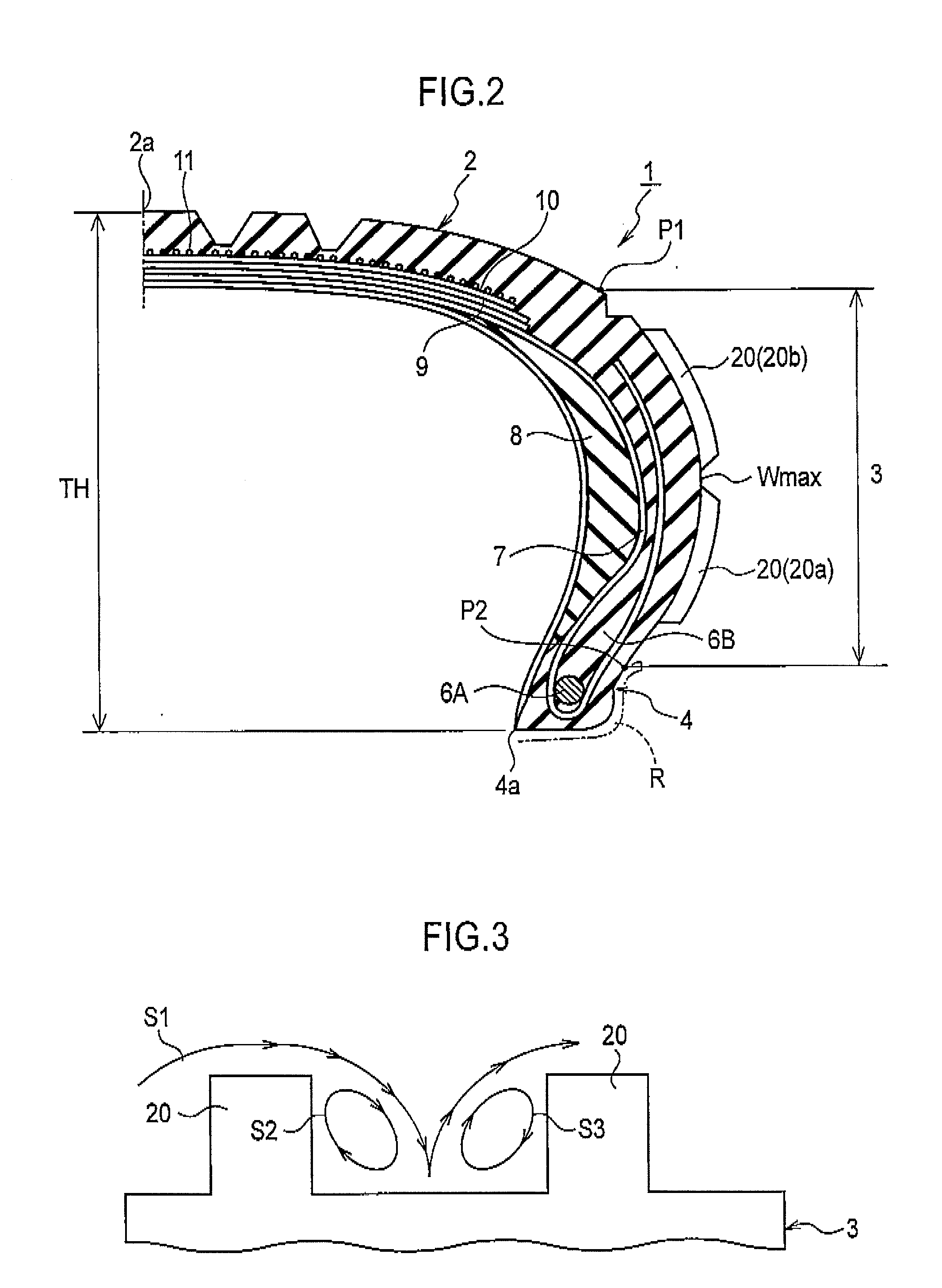
[0038]FIGS. 1 to 4 illustrate a run-flat tire 1, which is an example pneumatic tire according to Embodiment 1, and principal portions of the run-flat tire 1. FIG. 1 is a side elevation view illustrating the run-flat tire 1. FIG. 2 is a sectional view illustrating a principal portion taken along the line II-II of FIG. 1. FIG. 3 is a sectional view of turbulence generation ridges taken along the tire-circumferential direction. FIG. 4 is a perspective view illustrating a principal portion showing an example arrangement of turbulence generation ridges positioned at the inner side, in the tire-radial direction, of the tire maximum width position and turbulence generation ridges positioned at the outer side, in the tire-radial direction, of the tire maximum width position.

[0039]As FIGS. 1 and 2 show, the run-flat tire 1 roughly includes a tread portion 2, tire side portions 3, a...

modified examples

[0070]In the run-flat tire 1 of Embodiment 1, the turbulence generation ridges 20 formed on the outer surfaces of the tire side portions 3 are classified into two groups: the inner-side ridges 20a positioned at the inner side, in the tire-radial direction, of the tire maximum width position Wmax; and the outer-side ridges 20b positioned at the outer side, in the tire-radial direction, of the tire maximum width position Wmax. In addition, there are more inner-side ridges 20a formed than the outer-side ridges 20b. A Variety of alternative, specific arrangement patterns for the inner-side ridges 20a and the outer-side ridges 20b are possible other than the example pattern shown in FIGS. 1 and 4.

[0071]One of such alternative patterns is shown in FIGS. 5 and 6. In the pattern, a ring-shaped connection portion 20c is formed on the outer-side surface of each tire side portion 3 so as to be adjacent to the corresponding bead portion 4. The plural inner ridges 20a arranged radially around th...

example case a

[0090]For the purpose of confirming the effect of the invention, run-flat tires of Examples 1 to 7 and run-flat tires of Comparative Examples 1 to 3 were fabricated in accordance with the parameters listed in Table 1. The prototypes thus fabricated were subjected to durability drum testing under the following conditions to evaluate the durability and the travelling resistance for each prototype. Table 1 shows the evaluation results.

TABLE 1ComparativeComparativeComparativeExampleExampleExampleExampleExampleExampleExampleExample 1Example 2Example 31234567nowithwithwithwithwithwithwithwithwithParameterridgesridgesridgesridgesridgesridgesridgesridgesridgesridgesSum of—10040100100100100100100100SidewallAreas ofInner-SideRidges (Si)Sum of—10010050809030205040SidewallAreas ofOuter-SideRidges (So)So / Si (%)10025050809030205040Maximum—222222222Height h(mm)p / h of—123012121212121212Inner-SideRidgeProportion—1.31.32.61.61.44.36.42228of MaximumAreaWithoutOuter-SideRidge (%)RFT Drum501207810911611...


PUM


Abstract

The present invention includes a run-flat tire 1 comprising a plurality of turbulence generation ridges 20 which extend on a surface of a tire side portion 3 in a tire-radial direction and which are arranged at a pitch in a tire-circumferential direction and relationship Si>So is satisfied. Si is the sum of sidewall areas of all the turbulence generation ridges located at the inner side, in the tire-radial direction, of a maximum width position of the pneumatic tire. So is the sum of sidewall areas of all the turbulence generation ridges located at the outer side, in the tire-radial direction, of the tire maximum width position.

Description

CROSS REFERENCE TO RELATED APPLICATIONS[0001]This application is a National Stage of International Application No. PCT / JP2008 / 063692 filed Jul. 30, 2008, claiming priority based on Japanese Patent Application Nos. 2007-198175 and 2007-198182 both filed on Jul. 30, 2007, the contents of all of which are incorporated herein by reference in their entirety.TECHNICAL FIELD[0002]The invention relates to a pneumatic tire with a heat-dissipation function.BACKGROUND ART[0003]Generally, rise in temperature of a pneumatic tire is not favorable in view of the durability because the temperature rise accelerates over-time changes such as the changes in the properties of a material for the pneumatic tire or causes a break of a tread thereof during a high speed run. Lowering the temperature of the tire has been a significant desideratum to improve the durability especially for a run-flat tire in a case where a passenger vehicle with the run-flat tire is running while the run-flat tire is punctured ...

Claims


Application Information

Patent Timeline
IPC IPC(8): B60C13/02
CPCB60C17/0009B60C13/02B60C99/00
Inventor TSURUTA, MAKOTOYAMAGUCHI, MASASHIMIYASAKA, ATSUSHI
Owner BRIDGESTONE CORP
Why Eureka
Try Eureka