

Liquid circulation heating system
a heating system and liquid circulation technology, applied in the field of liquid circulation heating system, can solve the problems of low gwp, inconvenient use of hfo-1234yf, etc., and achieve the effect of less impact on global warming
- Summary
- Abstract
- Description
- Claims
- Application Information
AI Technical Summary
Benefits of technology
Problems solved by technology
Method used
Image

Examples
first embodiment
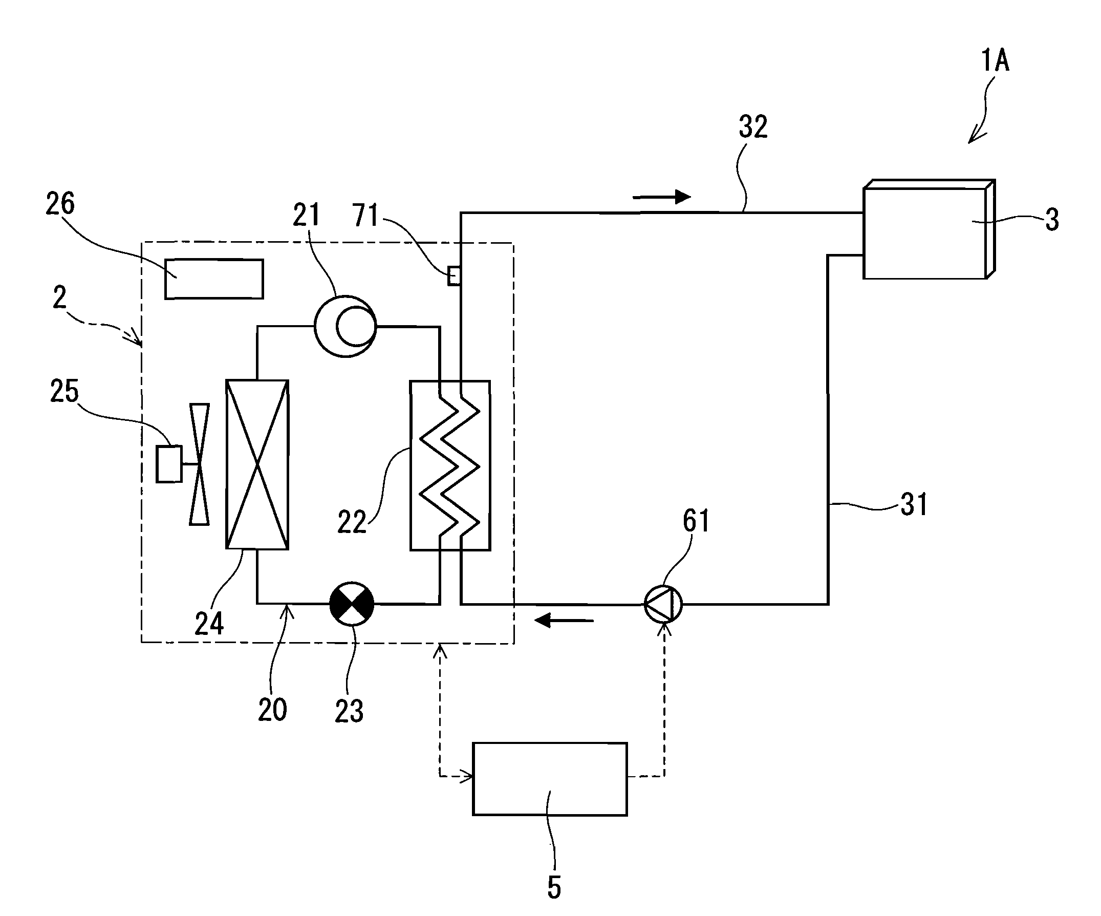
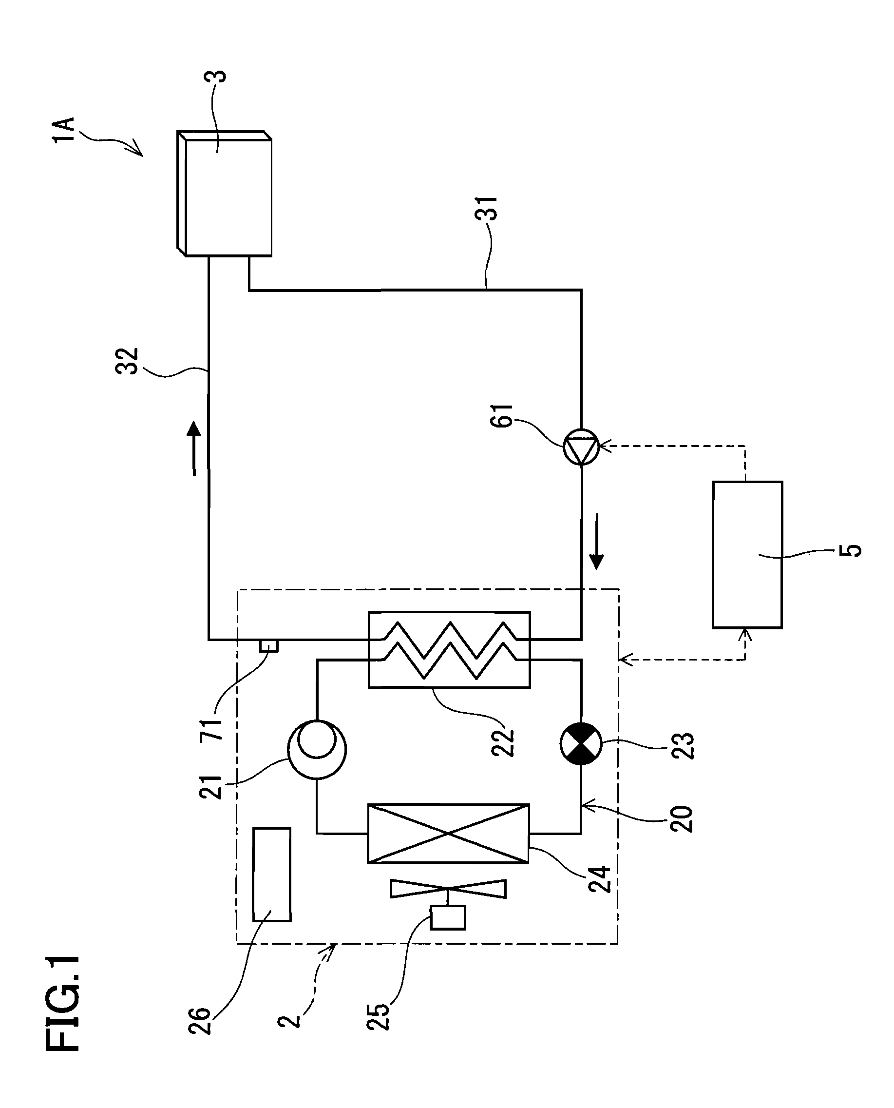
[0020]FIG. 1 shows a liquid circulation heating system 1A according to a first embodiment of the present invention. This liquid circulation heating system 1A heats a liquid to produce a heated liquid, releases heat of the heated liquid from a heating radiator 3, and thereby performs air-heating, for example, in a room. Specifically, the liquid circulation heating system 1A includes the heating radiator 3, a heat pump 2 for producing the heated liquid, and an overall controller 5 for controlling the entire system.
[0021]In the present embodiment, the heating radiator 3 is connected directly to the heat pump 2 by a supply pipe 31 and a recovery pipe 32 to be described later, so that the liquid flows without stopping. As the liquid, for example, an antifreeze liquid containing propylene glycol or the like dissolved in water can be used, but water is preferably used because it is available at low cost and in large quantities. The following description will be made on the assumption that ...
second embodiment
[0041]FIG. 5 shows a liquid circulation heating system 1B according to a second embodiment of the present invention. In the present embodiment, the same components as those in the first embodiment are designated by the same reference numerals and no further description is given.
[0042]The liquid circulation heating system 1B of the second embodiment has the same configuration as the liquid circulation heating system 1A of the first embodiment, except that the heating radiator 3 and the radiator 22 are connected via the hot water storage tank 8.
[0043]Furthermore, as a refrigerant for the heat pump 2, the same refrigerant as that described in the first embodiment also can be used in the present embodiment, and therefore the description of the refrigerant is not repeated here. The same description also is not repeated in the following embodiment and modifications.
[0044]The hot water storage tank 8 is a vertically cylindrical closed casing and is filled with water. The lower portion of t...
third embodiment
[0054]FIG. 6 shows a liquid circulation heating system 1C according to a third embodiment of the present invention. In the present embodiment, the same components as those in the first and second embodiments are designated by the same reference numerals and no further description is given.
[0055]In the liquid circulation heating system 1C of the third embodiment, hot water stored in the hot water storage tank 8 can be used directly for hot water supply. Specifically, the water inlet pipe 91 is connected to the lower portion of the hot water storage tank 8, and the hot water outlet pipe 93 is connected to the upper portion of the hot water storage tank 8. At an upper position in the hot water storage tank 8, a heat exchanger 83 for exchanging heat between the hot water stored in the hot water storage tank 8 and a heat transfer liquid (secondary liquid) is provided. The heat exchanger 83 is connected to the heating radiator 3 by the feed pipe 81 and the return pipe 82. When the circula...
PUM
 Abstract
Description
Claims
Application Information