
Object for authentication verification, authentication verifying chip reading device and authentication judging method

a technology of authentication verification and reading device, applied in the direction of paper-money testing device, instrument, electromagnetic radiation sensing device, etc., can solve the problems of ic card being much more expensive than magnetic card, card may not be absolutely safe when elaborate forgery is attempted, and card may not be absolutely sa

Active Publication Date: 2010-08-05
INT FRONTIER TECH LAB
View PDF4 Cites 15 Cited by
  • Summary
  • Abstract
  • Description
  • Claims
  • Application Information

AI Technical Summary

Benefits of technology

"The present invention provides a structure and method for producing an authentication verifying chip with a non-reproducible and copy-unable verification pattern. The chip has iridescence that can be viewed when incident light enters the chip, and the phase of the reflected light is strengthened when the phase of the light reflected at the surface of the chip matches the phase of the light reflected at the rear surface of the chip. The invention also provides means for reading and confirming the validity of the authentication information, as well as means for certifying the validity of the chip by the chip producer side using an authentication certifying chip."

Problems solved by technology

Because the information written in the magnetic stripe can be easily read by using a device called skimmer, the card is often forged and used, and this causes troubles and damages.
However, even in the case of this IC card, it is possible to read the information stored in the memory, and this card may not be absolutely safe when elaborate forgery is attempted.
In addition, the IC card is much more expensive compared with the magnetic card, and it would be hard to expect the rapid propagation of the IC card.
The credit card is a magnetic card used worldwide, and it is very difficult to replace it with the IC card of unified standards.
When these magnetic cards or IC cards are lost or stolen, the card owner may easily become aware of the loss or theft.
When the card comes back into the hand of the original owner after it has been stolen, and, in particular, when the card owner does not become aware of the fact that the card has been stolen, it is liable to cause damage by the use of the forged card.
Since assumable numbers have been often used for these personal identification numbers, there have been many cases of the loss and damage.
It is now very difficult to prevent the illegitimate use of cards by using the personal identification number.
Time and procedures are required for the registration of the pattern, and also, much time is needed for the recognition of the pattern itself, and that results higher costs.
In case of the contact type recognition, the user must directly touch a detection device, and this often causes physiological repugnance or disgust.
When the user has injury on the physical part necessary for the biometrical recognition, or in the worst case where the user has lost the physical part to be needed for the recognition, the biometrics recognition cannot be carried out.
Also, the recognition is partially made during the process of identifying, and accordingly, it is not a perfect method.
Further, in the system using the biometrical recognition where only the card owner himself or herself can use, even when the card owner wants to ask somebody to handle the card on behalf of the owner, who has not enough time to use the card personally or does not find a card processing device nearby, it is not allowed.
This causes much inconvenience to the user.
This embossed hologram is very difficult to copy, and it is practically impossible to forge the cards with the embossed hologram.
This method, thus, gives high effect in primary screening, but its reliability is low.
Even when these types of implements are used, final verification depends on human sense, and the reliability is low.
In this respect, there is a possibility that forgery can be made according to a copying technique.

Method used

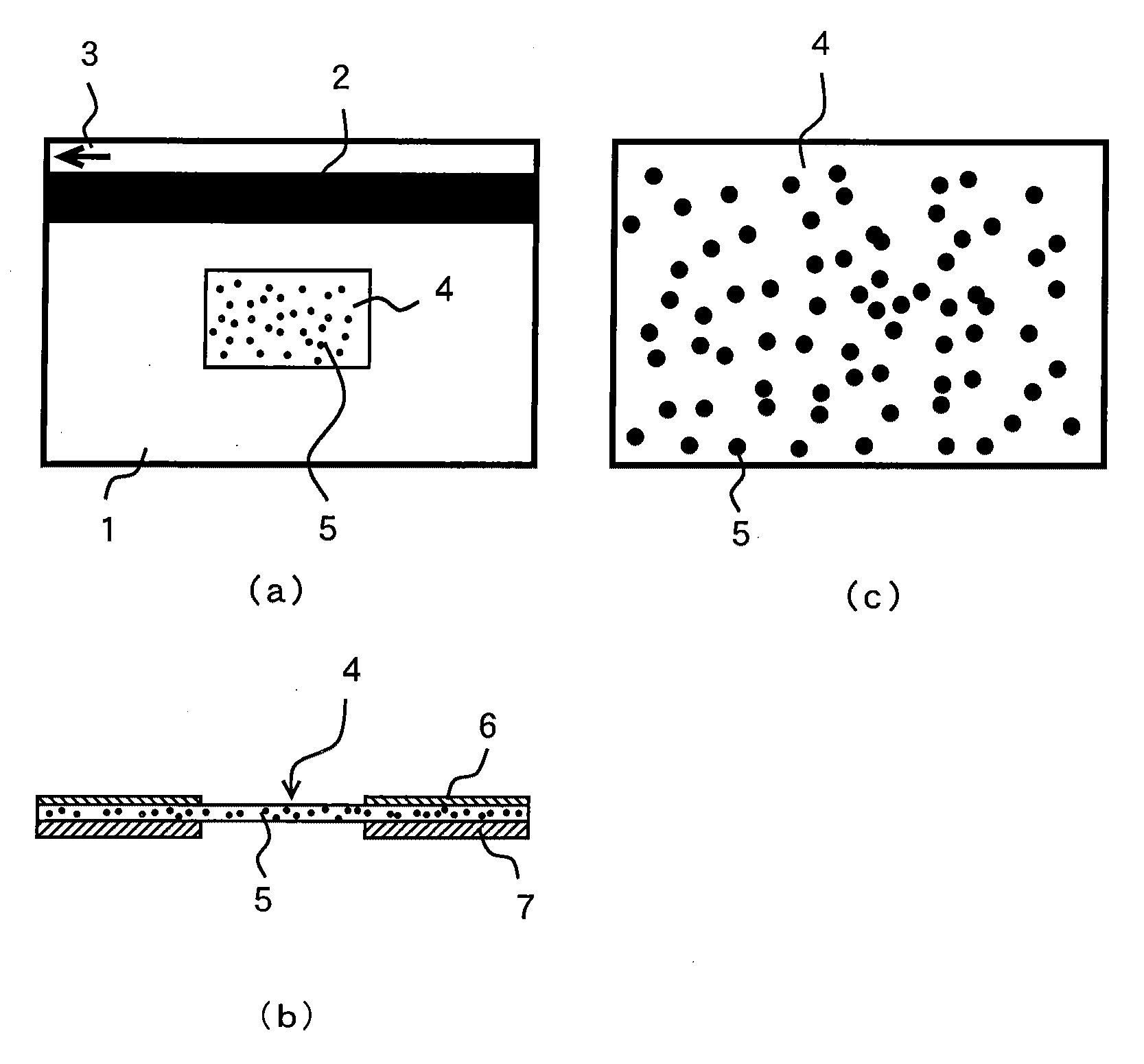
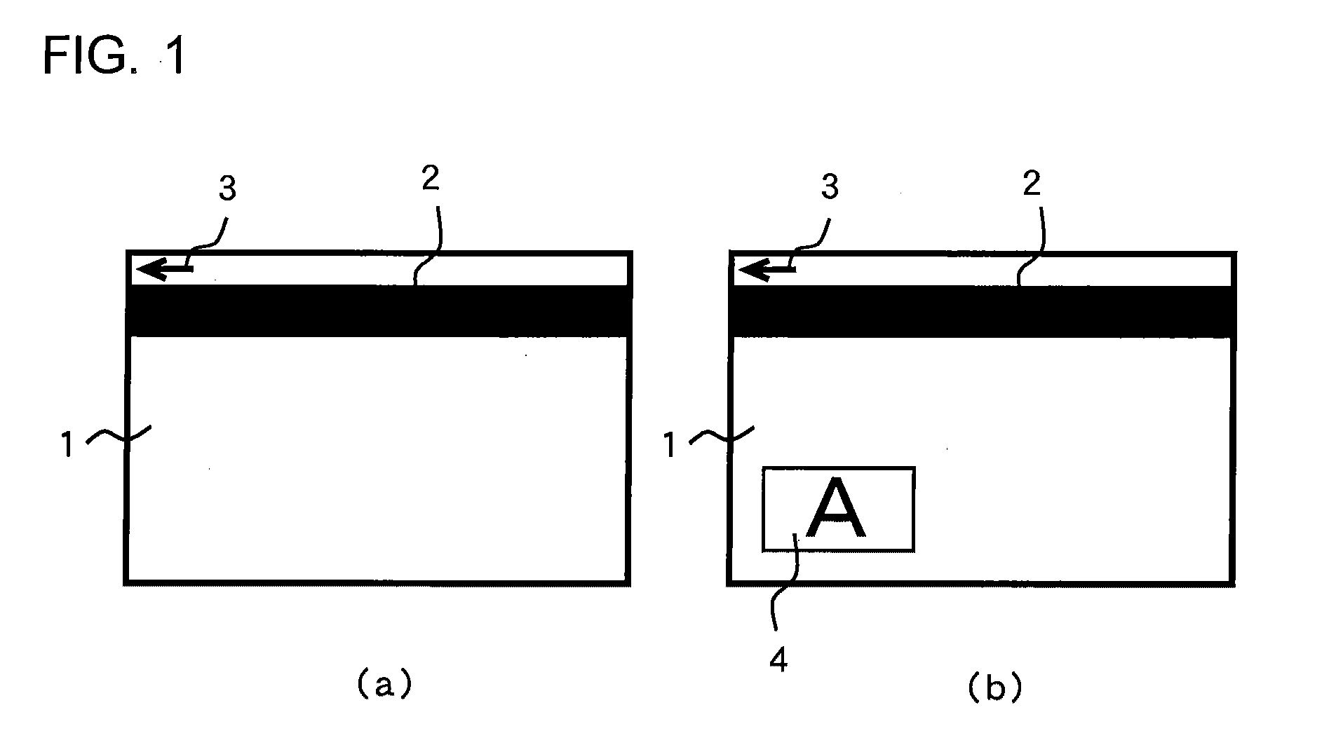
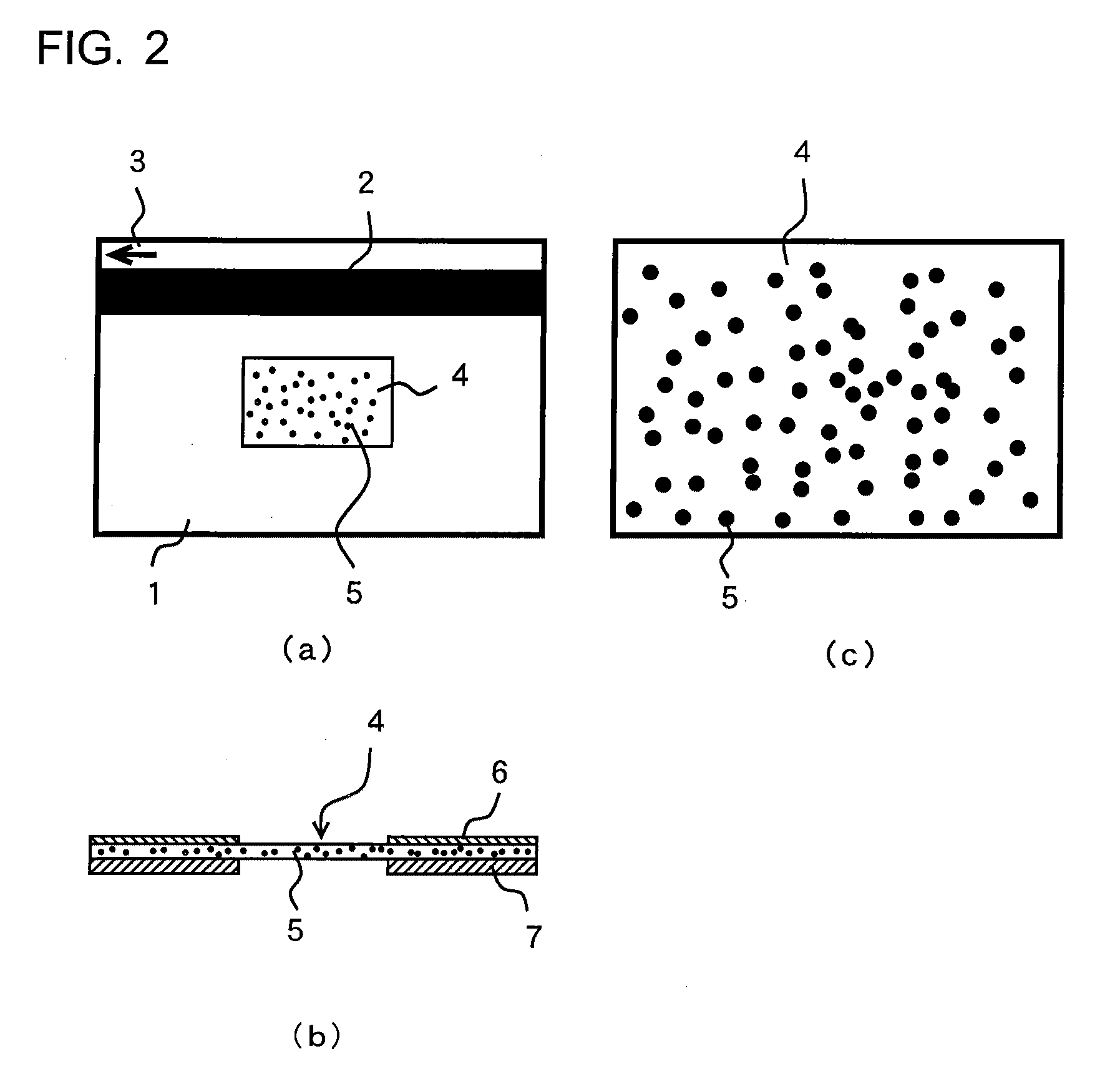

Image

  • Object for authentication verification, authentication verifying chip reading device and authentication judging method
  • Object for authentication verification, authentication verifying chip reading device and authentication judging method
  • Object for authentication verification, authentication verifying chip reading device and authentication judging method

Examples


embodiments

Authentication Verifying Chip

Embodiment 1

[0190]FIG. 9 shows an authentication verifying chip of Embodiment 1.

[0191]In this authentication verifying chip, only the perpendicularly entering lights are used as shown in FIG. 7 (a) and FIG. 7 (b).

[0192]FIG. 9 (a) is a view of a card as seen from above, FIG. 9 (b) is a cross-sectional view, FIG. 9 (c) is an enlarged cross-sectional view, and FIG. 9 (d) shows an example of an iridescence piece structure. In these figures, the reference numeral 61 represents a card body, which has a magnetic stripe 2 and an arrow mark 3 to indicate a card-inserting direction where an authentication verifying chip 62 is layered on a card base plate 63. The reference numeral 64 represents a surface plate, and other surface plates can be layered on the authentication verifying chip 62 and on the surface plate 64.

[0193]The base plate 63 is a thick synthetic resin plate as widely used in the cash card or the like, or a thin non-transparent synthetic resin plate ...

embodiment 2

[0205]FIG. 13 shows an authentication verifying chip of Embodiment 2. In the authentication verifying chip, in addition to the perpendicularly entering incident lights as shown in FIG. 7 (a) and FIG. 7 (b), inclined incident lights of λ3 or λ4 as shown in FIGS. 7 (c) and (d) are used.

[0206]In the authentication verifying chip 62 of the Embodiment 1, the iridescence pieces 66 are arranged only horizontally. In the authentication verifying chip 71 of the Embodiment 2, the iridescence pieces 66 are disposed in various different postures. In the authentication verifying chips 62 of the Embodiment 1, therefore, the iridescence pieces 66 different in thickness are needed for lights with different colors appearing, while the iridescence pieces 66 may have a single thickness in the Embodiment 2 authentication verifying chip 71.

[0207]In the authentication verifying chip 71, the incident lights to the iridescence pieces horizontally arranged are reflected in the same manner as in the Embodime...

embodiment 3

[0214]FIG. 14 shows an authentication verifying chip of Embodiment 3.

[0215]In the Embodiment 3, instead of the Embodiment 1 as shown in FIG. 9 and the Embodiment 2 as shown in FIG. 13 where iridescence pieces formed by PET resins or the like with a light reflection layer placed each in between are used, iridescence pieces formed by transparent media with the different thickness without a light reflection layer therein are used.

[0216]In the authentication verifying chip 72 as shown in FIG. 14 (a), iridescence pieces 73 made of a transparent medium and being different in thickness as shown by numerals 74 and 75 in FIG. 14 (b) are scattered at a bottom 70. A transparent resin 65 covers on the whole.

[0217]When a light enters the iridescence pieces 73, a part of it enters the iridescence pieces 73, and is then reflected at a reflection surface, i.e., at the opposite surface, and the light exits from the incident surface.

[0218]As a result, in this authentication verifying chip 72, the lig...


PUM

PropertyMeasurementUnit
depthaaaaaaaaaa
depthaaaaaaaaaa
depthaaaaaaaaaa

Abstract

A structure of a subject such as a card, a bank note, or a stock certificate easily faked and needing authenticity validation and a method for judging the authenticity of the subject. An authenticity validation chip having structural color developers irregularly arranged is attached to a card. An optical sensor detects the arrangement of the structural color developers to individually recognize the card or judge its authenticity. To validate the authenticity, when or after the card is taken in, the information in the authenticity validation chip provided on the card is read. Each of the structural color developers is a transparent resin flake or a transparent resin thin layer. The information is read two-dimensionally with a camera, and the authenticity of the authenticity validation chip is judged by observing the distributed state of the structural color developers. Alternatively, the information can be read linearly. A given straight or curved line can be used by altering the read portion while associating the shape of the read line with the movement of the card in taking in the card.

Description

FIELD OF THE INVENTION[0001]The present invention relates to a structure of an object such as a card, a bank note, securities, etc., which is often forged or counterfeited and which requires authentication to check whether it is authentic or not. The invention also relates to a method for verifying the authenticity of such the object.BACKGROUND ART[0002]In the present-day society, which is often called a card-oriented society, a wide variety of cards are used. There are cards relating to the assets of a property owner such as a bank cash card, a credit card of a credit company, a prepaid card such as securities, and identification cards such as a driver's license, a health insurance card and a passport.[0003]On many types of cards relating to the personal property or securities and bonds, necessary information is written on a magnetic stripe disposed on the surface or on the rear surface of the card. By using an automatic machine such as an ATM (automated teller machine) or a manual...

Claims


Application Information

Patent Timeline
Patent Type & Authority Applications(United States)
IPC IPC(8): G06K5/00G06K19/067G06K7/14
CPCG06K19/14Y10T156/1041G07D7/2033G07D7/0093G07D7/01
Inventor KOMATSU, NOBUAKINANJO, SHIN-ICHIRO
Owner INT FRONTIER TECH LAB
Learn More