Aircraft with Integrated Lift and Propulsion System

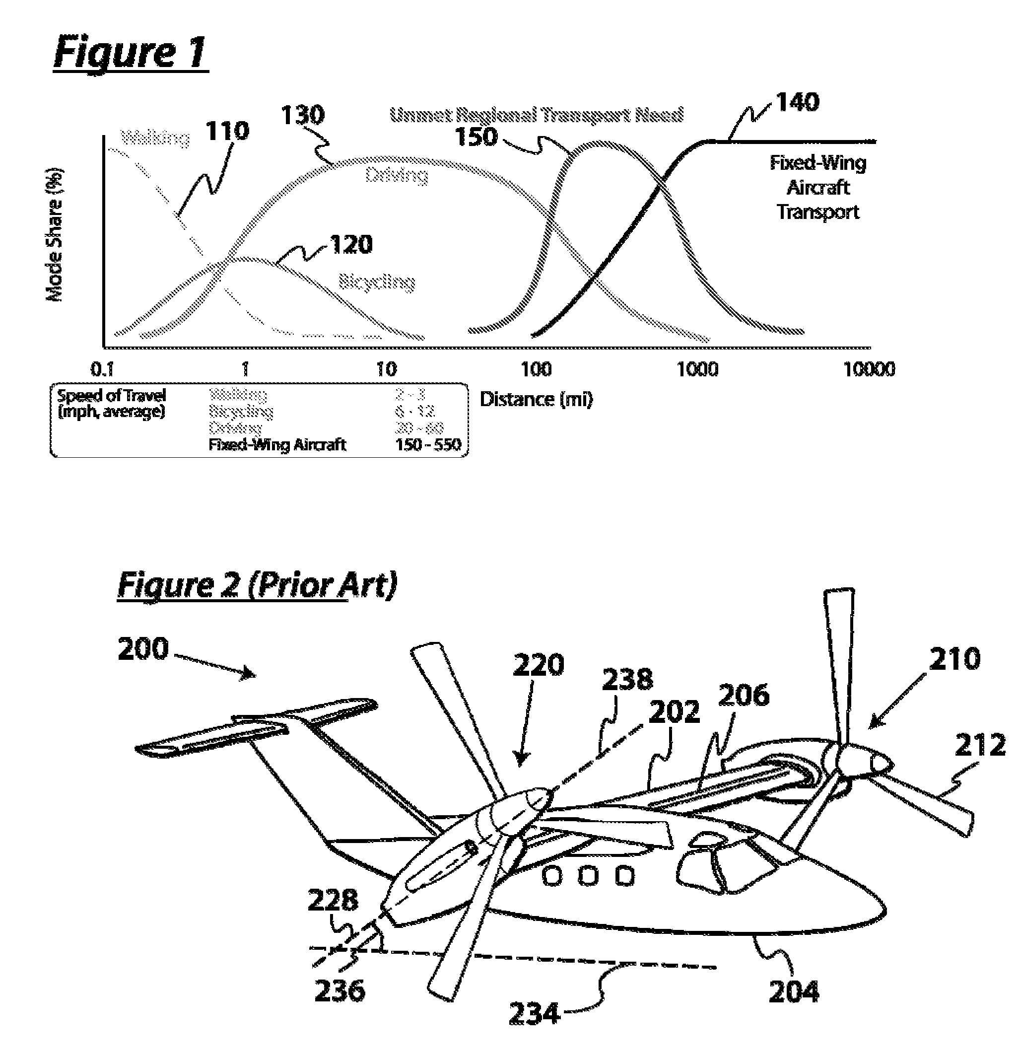
a propulsion system and aircraft technology, applied in the direction of vertical landing/take-off aircraft, aircraft navigation control, transportation and packaging, etc., can solve the problems of increasing the cost, driving down the speed of this travel mode, and reducing the efficiency of traditional fixed-wing air transportation for mid-range, or regional, trips between 100 and 1000 miles, so as to reduce the amount of engine power

Active Publication Date: 2010-08-05
KAREM ABE
View PDF14 Cites 76 Cited by
  • Summary
  • Abstract
  • Description
  • Claims
  • Application Information

AI Technical Summary

Benefits of technology

[0024]g. Low hover download to reduce the amount of engine power required for hover. (less than 5% of rotor lift vs. 11% the prior art Bell™ V-22 tilt-rotor).

Problems solved by technology

However, external factors such as rising fuel prices and increasing traffic congestion are driving down the speed of this travel mode and increasing its cost, especially relevant for trips over 100 miles.
However, there is a large overhead associated with this mode of travel, including travel to an airport, airport security lines, waiting for takeoff, and ground transport at the destination, all of which reduces the efficiency of traditional fixed-wing air transport for mid-range, or regional, trips between 100 and 1000 miles.
For regions with a dispersed population, including suburbanized regions, the cost of building rail infrastructure to connect a large percentage of the population is prohibitive.
However, despite decades of attempts, successful VTOL transport remains elusive due to challenging technical obstacles.
Among other things, prior art VTOL is prohibitively expensive to operate, has low flight speeds, limited ranges, is relatively fuel inefficient, and has a relatively poor safety record.
In the void left by the lack of a viable regional transportation method, passengers are relegated to driving long distances in increasingly congested traffic, or flying regional fixed-wing transport aircraft and enduring long airport-related waits.
The aircraft of FIG. 2 has a relatively small fuselage, a relatively small wing aspect ratio, and has gimbaled rotors not capable of variable speed operation.
Conventional helicopters, such as the modern Sikorsky™ S-92, are severely limited in terms of cruise speed and efficiency.
It is possible for the flow near the tip blade to achieve or exceed the speed of sound, and thus produce vastly increased drag and vibration.
This limits the forward speed of helicopters.
Additionally, a rotor is an inefficient way to generate lift as compared to a wing, partially due to the dissymmetry of lift between advancing and retreating sides of the rotor.
Prior art tilt-rotors have had short, low-aspect ratio wings that were relatively thick because they had to support heavy rotor systems, which results in lower efficiency, L / D, as compared to fixed-wing aircraft.
Despite marginal increases in speed and forward flight efficiency of tilt-rotor aircraft relative to helicopters, the prior art tilt-rotors have failed to improve on the productivity (how fast one transports a payload) of conventional helicopters.
The complexity, resulting high cost, aerodynamic inefficiency, poor safety record, and weight criticality of rotorcraft conspire to make them entirely uncompetitive with fixed-wing aircraft.
This would result in higher rotor disc loading in hover, and would constrain the wing to be short and thick to prevent the whirl flutter aeroelastic instability resulting from heavy conventional rotors at higher speeds.
Furthermore, the flight envelope would be constrained to lower speeds because of the thick wing, the efficiency would be reduced because of the short wing, and the cruise altitude would be capped by the small wing area.

Method used


Image

  • Aircraft with Integrated Lift and Propulsion System
  • Aircraft with Integrated Lift and Propulsion System
  • Aircraft with Integrated Lift and Propulsion System

Examples


Embodiment Construction

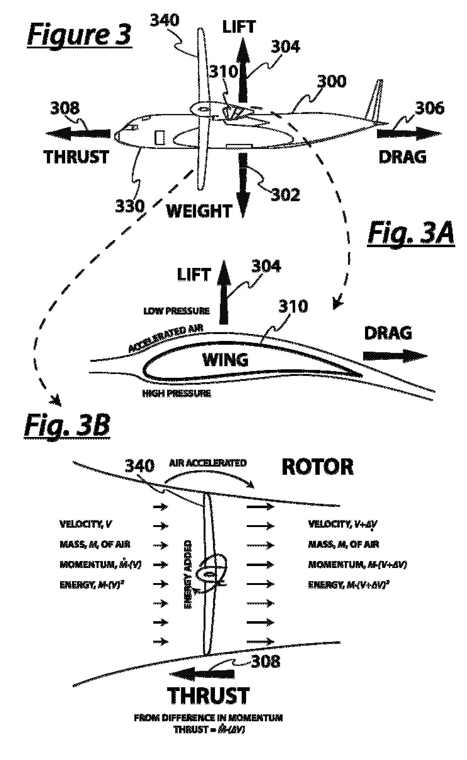
[0050]Physics of Efficient Flight p As shown in the side view illustration of FIG. 3, a preferred aircraft 300 in non-accelerated flight is in force equilibrium. Its weight 302 is balanced by the same amount of lift 304, and the aerodynamic resistance to its motion, drag 306, is countered by a propelling thrust 308. An aircraft in steady level equilibrium flight is said to be in cruise flight.

[0051]The generation of thrust requires energy, often produced via combustion in a turbine engine. Efficient flight minimizes the amount of energy added, or equivalently, the amount of fuel burned to maintain equilibrium flight.

[0052]FIG. 3A provides detail of the wing 310 while FIG. 3B provides detail of the rotor 340.

[0053]A flying machine must generate lift 304 and thrust 308 forces to fly. Lift is generated by air pressure differences across lifting surfaces, especially wings 310. However, lifting surfaces also generate some drag, including induced drag, due to the direction of the generate...


PUM


Abstract

A vertical take off and landing (VTOL) aircraft is designed to be so efficient that it can be commercially competitive with runway dependent aircraft operating in a range of 100 to 1000 miles. Improvements include a high efficiency tilting rotor and wing design that enable both vertical takeoff and efficient high speed cruising, a high aspect ratio wing, and a variable speed propulsion system that is efficient in both hover and cruise flight. Preferred aircraft use thin inboard and outboard wings, thin rotor blades, and use efficient lightweight design to achieve unusually low empty weight fraction. Inventive methods include utilization of advanced design and analysis techniques, which allow for accurate prediction of an aircraft's physical behavior.

Description

[0001]This application claims priority to provisional application Ser. No. 61 / 047,844 filed Apr. 25, 2008, which is incorporated by reference herein in its entirety.FIELD OF THE INVENTION[0002]The field of the invention is high efficiency vertical takeoff aircraft.BACKGROUND[0003]Passenger transit can be broken down into categories based on the length of the trip as shown in FIG. 1. For short trip distances, under 2 miles, the transit modes of walking 110, and bicycling 120 are preferred: they require very little overhead (non-travel time associated with the trip, such as putting on shoes) but are very slow. For somewhat longer trips, between 2 and 200 miles, driving 130 is the preferred mode of travel. However, external factors such as rising fuel prices and increasing traffic congestion are driving down the speed of this travel mode and increasing its cost, especially relevant for trips over 100 miles. Fixed-wing air travel 140 offers high trip speeds, and is usually preferred for...

Claims


Application Information

Patent Timeline
Patent Type & Authority Applications(United States)
IPC IPC(8): B64C27/28B64C29/00B64C27/26B64C27/22
CPCB64C3/10B64C27/28B64C3/385B64C29/0033Y02T50/12B64C27/467Y02T50/10
Inventor KAREM, ABE
Owner KAREM ABE
Why Eureka
Try Eureka