

Side vehicle-body structure of vehicle
a vehicle body and side vehicle technology, applied in the direction of roofs, vehicle arrangements, transportation and packaging, etc., can solve the problems of improper increase of the weight rather complex structure of the center pillar, etc., and achieve the effect of simple structur
- Summary
- Abstract
- Description
- Claims
- Application Information
AI Technical Summary
Benefits of technology
Problems solved by technology
Method used
Image


Examples
Embodiment Construction
[0031]Hereinafter, a preferred embodiment of the present invention will be described referring to the accompanying drawings.
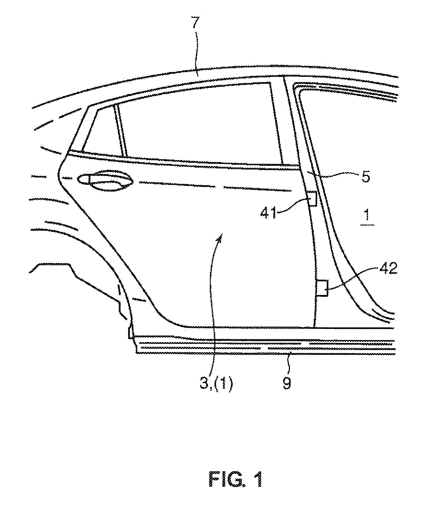
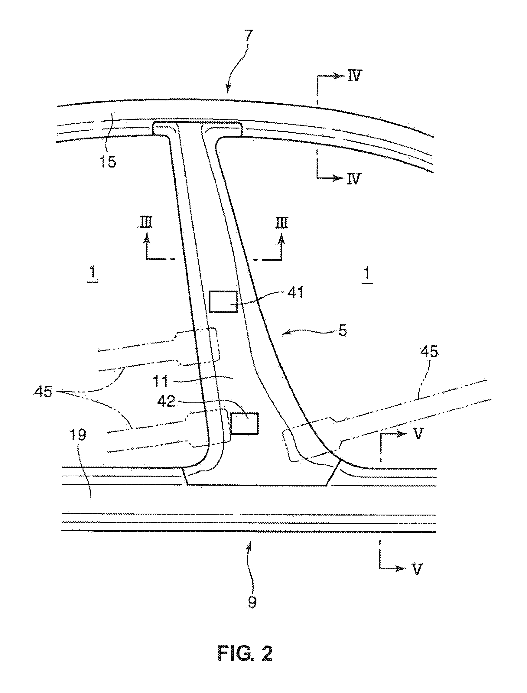
[0032]FIGS. 1 and 2 show a side vehicle-body structure of a vehicle according an embodiment of the present invention. An opening for ingress or egress 1 is formed at a side face of the vehicle shown in these figures, and this opening 1 is closable with a side door 3 (see FIG. 1). Herein, a four-door sedan type of automotive vehicle is exemplified, in which two openings 1 are arranged at both sides of the vehicle body in front of and in back of a center pillar 5, which will be described, and two side doors 3 are provided at these openings 1. Herein, a front-side side door (front side door) is omitted in FIG. 1, and the side door 3 illustrated is a rear side door which closes the rear opening 1.
[0033]A roof side rail 7 and a side sill 9 which extend in the longitudinal direction are provided at a side portion of the vehicle, which form an upper side and a lower s...
PUM
 Abstract
Description
Claims
Application Information