Safety Photoelectric Switch

a photoelectric switch and safety technology, applied in the direction of electronic switching, pulse technique, instruments, etc., can solve the problem of a new photoelectric switch appearing, and achieve the effect of suppressing the influence of the change on the detection sensitivity

Active Publication Date: 2010-08-05
KEYENCE
View PDF23 Cites 76 Cited by
  • Summary
  • Abstract
  • Description
  • Claims
  • Application Information

AI Technical Summary

Benefits of technology

[0010]Even when the interference with another photoelectric switch occurs once, the light projection period, the scanning period or the phase of the light projection pulse with respect to the light projection period is changed, so as to prevent the interference from occurring twice in succession. Therefore, when it is determined at least twice in succession that the position of the object is inside the protection area, the non-permission signal is outputted, so that a problem concerning the interference with another photoelectric switch can be solved.
[0011]In a preferred embodiment of the present invention, the light projection pulse has a predetermined pulse width, and the light projection period or the scanning period is changed without changing the pulse width of the light projection pulse. Accordingly, even when the light projection period or the scanning period is changed, an influence by the change upon a detection sensitivity can be suppressed.

Problems solved by technology

Since this optical scanning type photoelectric switch scans a two-dimensional plane in a broad range, when another photoelectric switch is present adjacently thereto, a problem of interference with this another photoelectric switch tends to occur.

Method used


Image

  • Safety Photoelectric Switch
  • Safety Photoelectric Switch
  • Safety Photoelectric Switch

Examples


examples

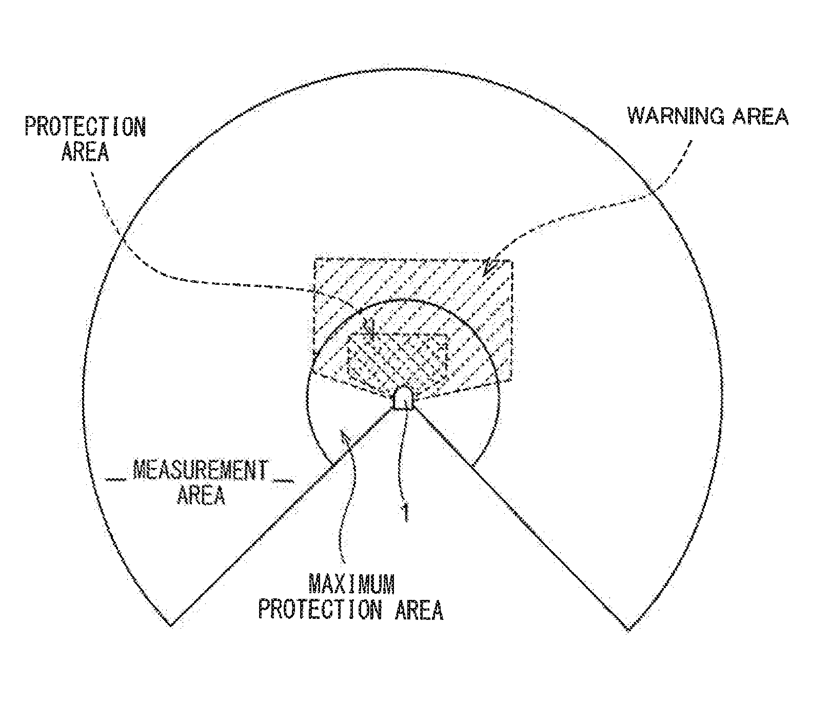
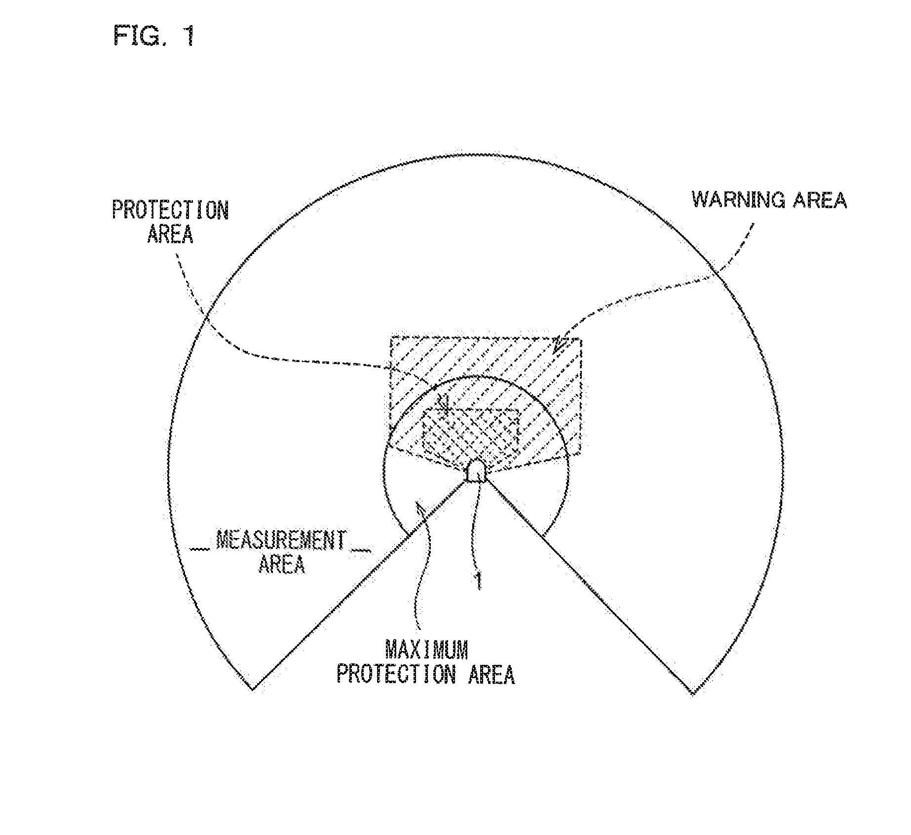
[0068]With reference to FIG. 1, as generalities, basic terms of an optical scanning type photoelectric switch: “measurement area”; “maximum protection area”; “warning area”; and “protection area”, are described. The “maximum protection area” means a region where objects having a variety of reflection factors from a low reflection factor object to a high reflection factor object, which are stipulated by the safety standard, are detectable by the optical scanning type photoelectric switch. The “measurement area” means a region where an object having a standard reflection factor is detectable by the optical scanning type photoelectric switch, and this “measurement area” completely includes the “maximum protection area”.

[0069]As is known, the optical scanning type photoelectric switch is used to two-dimensionally scan the maximum protection area with light such as laser light and monitor scanning light reflected from the maximum protection area, thereby to monitor safety inside the area...


PUM

PropertyMeasurementUnit
radial distanceaaaaaaaaaa
scan angleaaaaaaaaaa
angleaaaaaaaaaa

Abstract

There is provided an optical scanning type photoelectric switch capable of preventing interference with another photoelectric switch by use of its own capability, wherein, as for light projection pulse periods of the first and second optical scanning type photoelectric switches, the period is set to 30 μs in the first optical scanning type photoelectric switch while the period is set to 33 μs in the second optical scanning type photoelectric switch 1B, the light projection pulses have the same pulse width, and by setting the light projection periods different between the first and second optical scanning type photoelectric switches, even if mutual interference occurs between any optical axes, a phase difference of 36 degrees in rotation period is generated therebetween in a next scan, thereby preventing occurrence of the interference in succession in a plurality of times of scanning.

Description

CROSS REFERENCE TO RELATED APPLICATIONS[0001]The present application claims foreign priority based on Japanese Patent Application No. 2009-021046, filed Jan. 31, 2009, the contents of which is incorporated herein by reference.BACKGROUND OF THE INVENTION[0002]1. Field of the Invention[0003]The present invention relates to a safety photoelectric switch.[0004]2. Description of the Background Art[0005]As seen in Japanese Patent Application Laid-Open No. H4-310890 and Japanese Patent Application Laid-Open No. H3-175390, an optical scanning type photoelectric switch is known which two-dimensionally performs scanning with light to detect an object while detecting a position of this object. As also referred to as a safety scanner, a safety laser scanner, and the like, this optical scanning type photoelectric switch provides a protection area around a machine, a robot or the like as a danger source, and outputs to the danger source a safety signal not permitting its operation when an operato...

Claims


Application Information

Patent Timeline
Patent Type & Authority Applications(United States)
IPC IPC(8): G08C19/16G01S17/04G01S17/931
CPCG01S7/4812G01S7/4813G01S7/4817G01S17/42G01S17/88G01V8/18H03K17/941F16P3/12F16P3/141F16P3/144F16P3/147G01V8/14G01V8/20G01S17/04G01S17/931
Inventor KAWABATA, SHINJI
Owner KEYENCE
Why Eureka
Try Eureka