Three-dimensional measuring device and board inspection device

Active Publication Date: 2010-08-05
CKD
View PDF2 Cites 29 Cited by
  • Summary
  • Abstract
  • Description
  • Claims
  • Application Information

AI Technical Summary

Benefits of technology

[0019]According to the first and second aspects of the present invention, at least height of the measurement object part is calculated using the phase shift method by the first calculation means based on a multiplicity of image data imaged by the imaging means. Further, either beforehand or simultaneously therewith, the second calculation means uses the spatial encoding method to identify a line corresponding to the measurement object part from among the image data during calculation by the first calculation means using the phase shift method based on the image data imaged by the imaging means. That is to say, the line corresponding to the measurement object part in the phase shift method is identified (i.e., the line order is identified), and the first calculation means uses this line for calculation of height of the measurement object part by the first calculation means. As a result, it becomes possible to realize both the effects of increasing the height range capable of measurement, which is an advantage of the spatial encoding method, and realizing highly accurate measurement, which is an advantage of the phase shift method.
[0020]The imaging control means also controls imaging by the imaging means. Particularly, the imaging control means in the second aspect, based on design data and/or production dat

Problems solved by technology

If the gaps between the lines of the irradiated light pattern are widened in order to adjust to the maximum height among such measurement objects, resolution ability becomes poor, and there is concern that measurement accuracy will worsen.
On the other hand, although attempting to improve accuracy may be possible by narrowing the gaps between the lines, this then results in concern that the height range which is capable of measurement would become insufficient (such narrow gaps would result i

Method used


Image

  • Three-dimensional measuring device and board inspection device
  • Three-dimensional measuring device and board inspection device
  • Three-dimensional measuring device and board inspection device

Examples


Embodiment Construction

[0047]An embodiment will be explained below with reference to the figures.

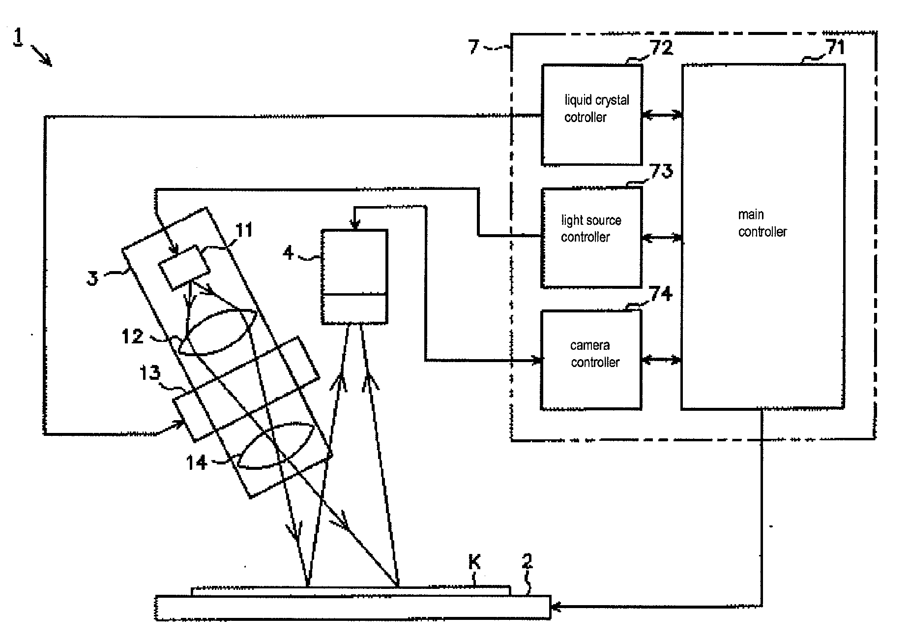
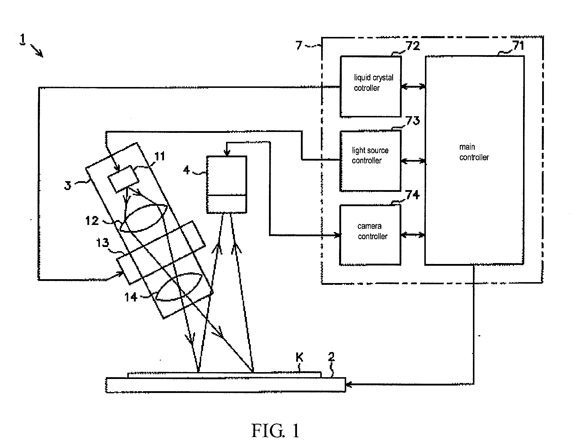
[0048]FIG. 1 is a simplified configuration drawing showing schematically a board inspection device 1 equipped with a three-dimensional measurement device of the present embodiment. As shown in FIG. 1, the board inspection device 1 is equipped with a conveyer 2 for carrying a printed circuit board K printed with a cream solder forming the inspection object, an irradiation means 3 for irradiating a certain light pattern obliquely from above onto the surface of the printed circuit board K, and a CCD camera 4 as an imaging means for imaging a region illuminated by the above-described irradiation on the printed circuit board K. A cream solder C in the present embodiment is formed and printed on an electrode pattern formed from copper foil provided on the printed circuit board K. Further, solder plating is provided on the electrode pattern. The above-described conveyer 2 is configured so as to move the printed circu...


PUM


Abstract

A three-dimensional measuring device includes an irradiation means capable of irradiating a striped light pattern used for a spatial encoding method and a striped light pattern used for a phase shift method on a measurement object part on a board main body, an imaging means capable of imaging a measurement object part irradiated by the light pattern, an image control means for controlling imaging by the imaging means, a first calculation means for calculating a height of the measurement object part according to the phase shift method based on a multiplicity of image data imaged by the imaging means, and a second calculation means capable of using the spatial encoding method to identify a line corresponding to the measurement object part from among the image data at a time of calculation by the first calculation means by the phase shift method based on the image data.

Description

CROSS-REFERENCE TO RELATED APPLICATIONS[0001]This application is a national stage application of International Application No. PCT / JP2008 / 062985 filed on Jul. 18, 2008, which claims priority to Japanese Patent Application No. 2007-206112 filed on Aug. 8, 2007 in Japan.BACKGROUND OF INVENTION[0002]1. Field of the Invention[0003]The present invention relates to a three-dimensional measuring device and a board inspection device equipped with this three-dimensional measuring device.[0004]2. Background Art[0005]When an electronic component is mounted on a printed circuit board, a cream solder is generally first printed on a specific electrode pattern disposed on the printed circuit board. Adhesivity of this cream solder is then used to temporarily fix the electronic component on the printed circuit board. Thereafter, the above-described printed circuit board is conveyed to a reflow furnace, and soldering is performed by a routine reflow process. Recently, it has become necessary to perfo...

Claims


Application Information

Patent Timeline
IPC IPC(8): H04N13/00
CPCG01B11/25H05K3/3484H05K1/0269G01N21/95684H05K3/3485G01N21/17G01N21/956H05K3/00
Inventor MAMIYA, TAKAHIRO
Owner CKD
Why Eureka
Try Eureka